In the alumina vs alumina substrate debate—96% versus 99.6% purity—the difference comes down to purity-driven trade-offs: 99.6% Al2O3 delivers roughly 30–40% higher thermal conductivity (28–35 W/mK vs 24–28 W/mK at 25 °C), tighter surface roughness, and better high-frequency dielectric performance, but it costs two to three times more per substrate and is harder to source in large panels. For most power and sensor applications below 10 GHz, 96% alumina is the practical choice. You move to 99.6% when thermal margin, surface finish, or loss tangent at millimetre-wave frequencies demands it.
Key Takeaways
- 96% alumina thermal conductivity is 24–28 W/mK at 25 °C; 99.6% alumina reaches 28–35 W/mK under the same conditions (per Kyocera A-493 and A-499 datasheets).
- Loss tangent at 1 MHz: 96% alumina ≈ 0.0002–0.0010; 99.6% alumina ≈ 0.0001–0.0004, making the higher grade preferable above ~20 GHz.
- As-fired surface roughness (Ra) for 99.6% alumina can be held under 0.25 µm; 96% alumina typically runs 0.5–1.0 µm without lapping.
- 99.6% alumina substrates generally cost 2–3× more than equivalent 96% substrates, driven by raw-material purity and tighter sintering controls.
- Both grades are compatible with DBC, DPC, thick-film, and thin-film metallisation processes.
Alumina vs Alumina Substrate: What Makes the Two Grades Different
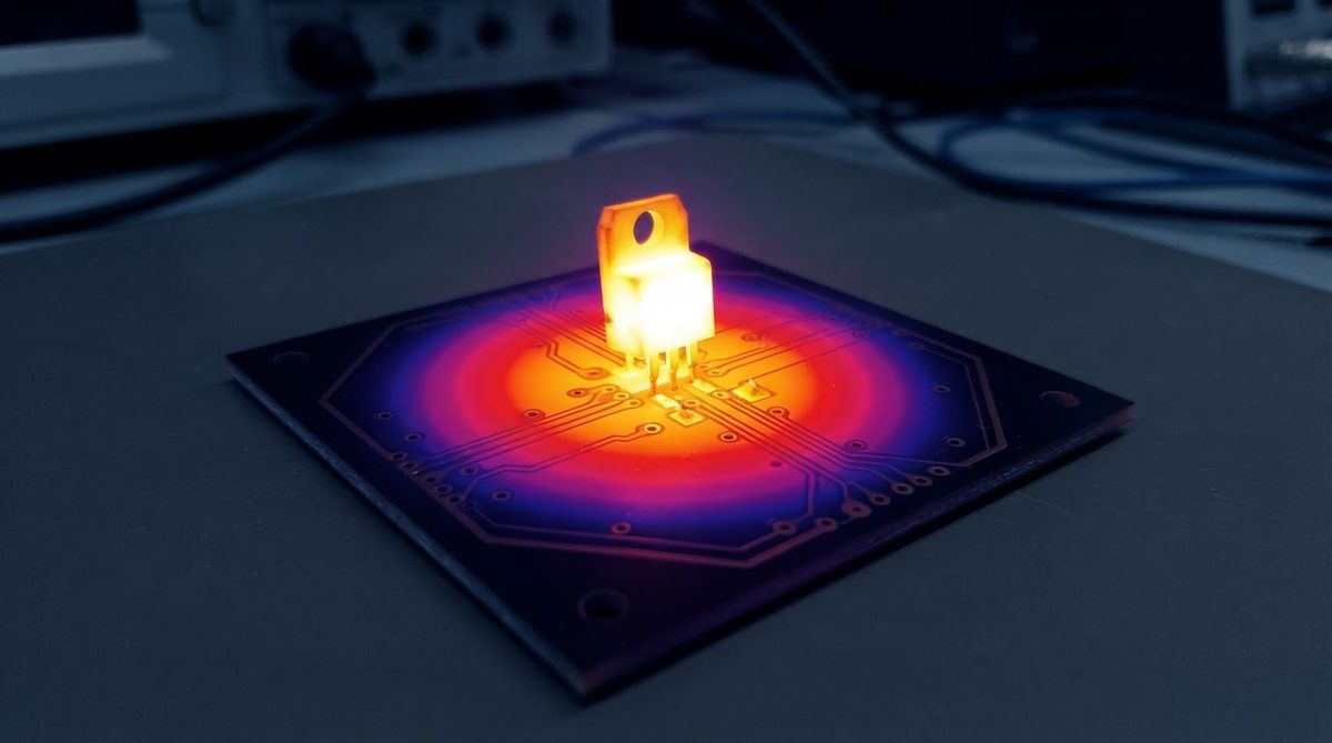
Both substrates are aluminium oxide. The number—96% or 99.6%—refers to the weight fraction of Al2O3 after sintering. The remaining material is a glass-phase binder (typically SiO2, MgO, and CaO in 96% bodies) that lowers the sintering temperature and makes the ceramic easier to manufacture. In 99.6% alumina the binder content is minimal, so the microstructure is almost entirely crystalline α-Al2O3.
That difference in glass content drives every specification gap in this alumina vs alumina substrate comparison. Glass phases scatter phonons (reducing thermal conductivity), introduce dielectric loss, lower mechanical strength at elevated temperatures, and roughen the as-fired surface because glass grains are softer and polish unevenly. Remove the glass and you get a substrate that is thermally, electrically, and mechanically superior—but harder and more expensive to sinter, machine, and laser-scribe.
For a broader view of how alumina compares with entirely different ceramic chemistries, see the 96% alumina versus AlN substrate comparison.
Property-by-Property Comparison Table
| Parameter | 96% Al2O3 | 99.6% Al2O3 | Unit | Condition | Source |
|---|---|---|---|---|---|
| Thermal conductivity | 24–28 | 28–35 | W/mK | 25 °C | Kyocera A-493 / A-499 |
| CTE | 7.1–8.0 | 7.1–8.2 | ppm/°C | 25–400 °C, ASTM E228 | CoorsTek ADS-996 / AD-96 |
| Dielectric constant (εr) | 9.0–9.5 | 9.7–10.1 | — | 1 MHz, 25 °C | Kyocera A-493 / A-499 |
| Loss tangent (tan δ) | 0.0002–0.0010 | 0.0001–0.0004 | — | 1 MHz, 25 °C | Kyocera A-493 / A-499 |
| Dielectric strength | 10–15 | 12–17 | kV/mm | AC, 60 Hz, 25 °C | CeramTec Rubalit 708 / 710 |
| Flexural strength | 340–380 | 350–400 | MPa | 4-pt bend, ASTM C1161 | Maruwa HA-96 / HA-996 |
| Surface roughness (Ra, as-fired) | 0.5–1.0 | 0.15–0.40 | µm | — | Maruwa HA-996 |
| Max continuous use temp. | 1 600 | 1 700 | °C | In air, no load | CoorsTek |
| Volume resistivity | >1014 | >1014 | Ω·cm | 25 °C | Kyocera |
| Relative substrate cost | 1× | 2–3× | — | Same footprint, qty 500 | Industry pricing, 2024 |
Typical values for commercially available material, for comparison only. Confirm against the datasheet for your specific grade.
Download the full property sheets directly: 96% alumina substrate datasheet and 99.6% alumina substrate datasheet.
Thermal Conductivity: When the 30–40% Gain Matters
The thermal conductivity gap in this alumina vs alumina substrate decision is real but modest in absolute terms—roughly 4–7 W/mK. Compare that with the jump to aluminum nitride (170–200 W/mK) and it is clear that switching from 96% to 99.6% alumina is a fine-tuning move, not a step change. It matters most in designs where:
- The substrate is thin (<0.38 mm) and thermal resistance through the ceramic dominates the stack.
- Multiple heat sources sit close together, making lateral spreading important.
- The design is already validated on alumina and the team needs a few more degrees of margin without re-qualifying a new material chemistry.
Worked Example: Thermal Resistance Through a 0.635 mm Substrate
Assume a 10 mm × 10 mm heat source dissipating 5 W through a 0.635 mm thick alumina substrate. One-dimensional thermal resistance Rth = t / (k × A).
96% alumina (k = 26 W/mK): Rth = 0.000635 / (26 × 0.0001) = 0.244 °C/W → ΔT = 1.22 °C
99.6% alumina (k = 32 W/mK): Rth = 0.000635 / (32 × 0.0001) = 0.198 °C/W → ΔT = 0.99 °C
The 99.6% grade saves about 0.23 °C at 5 W. At 50 W on the same footprint, that becomes 2.3 °C—meaningful in a tight thermal budget but unlikely to justify a 2–3× cost increase on its own. If you need a larger thermal gain, an alumina-to-AlN upgrade is a more effective lever.
Enter your own substrate dimensions and power dissipation below to see how the two grades compare for your specific layout.
Dielectric Performance and RF Applications
At frequencies below about 10 GHz, both grades perform well as microstrip or stripline substrates. The glass phase in 96% alumina introduces slightly higher dielectric loss, but tan δ values around 0.0005 at 1 MHz are still low enough for most power-conversion and sensor circuits.
Above 20 GHz—Ka-band radar, 5G mmWave front-ends, satellite transponders—the lower and more consistent loss tangent of 99.6% alumina becomes significant. Insertion loss scales with frequency and tan δ, so halving the loss tangent roughly halves the dielectric contribution to line loss at any given frequency. For circuits operating at 60–77 GHz (automotive radar, WiGig), 99.6% alumina is the standard grade specified. If you are comparing metallisation approaches for these high-frequency substrates, the thick-film versus thin-film process comparison covers conductor-loss implications.
Note that the dielectric constant also shifts slightly: 99.6% alumina runs about 0.5–0.7 units higher (εr ≈ 9.8–10.1 vs 9.0–9.5). This changes impedance-controlled line widths. Re-simulate; do not assume a drop-in swap.
Surface Finish and Thin-Film Compatibility
Thin-film metallisation (sputtered Ti/Cu, TaN resistors, NiCr) requires a smooth, defect-free substrate surface. 99.6% alumina’s as-fired Ra of 0.15–0.40 µm meets most thin-film process requirements without lapping. 96% alumina at Ra 0.5–1.0 µm often needs a lapping step to bring roughness below 0.25 µm, adding cost and lead time.
If your design uses thick-film (screen-printed Ag, AgPd, or Au conductors), both grades work without additional surface preparation. The rougher surface of 96% alumina can actually improve paste adhesion during firing. For a detailed look at how DPC and thin-film processes differ, see the dedicated comparison.
Mechanical Considerations
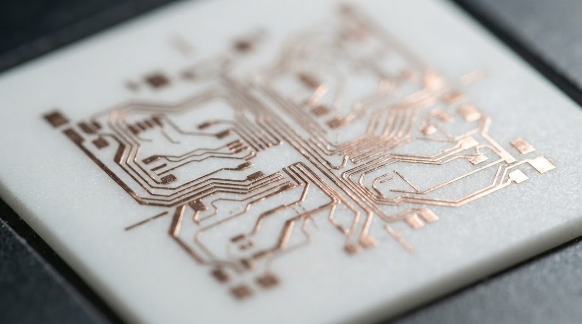
Flexural strength is similar between the two grades—both fall in the 340–400 MPa range per ASTM C1161. The practical difference is that 99.6% alumina, with its finer and more uniform grain structure, shows less scatter in strength data (tighter Weibull modulus). This matters for high-reliability applications where you design to the lower tail of the strength distribution, not the mean.
Both grades machine similarly with diamond tooling and laser scribing. 99.6% alumina is marginally harder (Vickers HV ≈ 1 500–1 600 vs 1 300–1 400 for 96%), so tool wear is slightly higher. For available substrate formats and tolerances, review the 96% alumina thickness and tolerance options.
When NOT to Use 99.6% Alumina
Choosing the higher-purity grade is not always the right call. Avoid 99.6% alumina when:
- Cost is the primary driver. At 2–3× the substrate price, the upgrade must deliver measurable system-level value. If your thermal analysis shows adequate margin on 96%, spend the budget elsewhere.
- You need a large panel or non-standard size. 99.6% alumina is produced in smaller volumes and fewer standard panel sizes. Lead times are longer and minimum order quantities are higher.
- Your application operates below 10 GHz with thick-film conductors. The dielectric and surface-finish advantages of 99.6% alumina are largely invisible in this regime.
- You actually need a thermal conductivity above 35 W/mK. Neither alumina grade will get you there. Move to aluminum nitride (170–200 W/mK) or, for extreme mechanical loads, silicon nitride substrates.
Decision Checklist: Alumina vs Alumina Substrate Grade Selection
Run through these five questions for your specific board. If you answer “yes” to two or more, 99.6% alumina is likely justified.
- Is the operating frequency above 20 GHz?
- Does the design use sputtered or evaporated thin-film metallisation?
- Is the substrate thinner than 0.38 mm with a thermal budget under 5 °C through the ceramic?
- Does your reliability spec require Weibull-qualified mechanical strength data?
- Is hermetic sealing to the substrate required (brazed lids, glass-sealed feedthroughs)?
If none of these apply, 96% alumina will serve the design at lower cost and shorter lead time. The alumina vs alumina substrate choice should always be driven by measurable system requirements, not a general preference for higher purity.
Frequently Asked Questions
Can I swap 96% alumina for 99.6% without redesigning the circuit?
Not directly. The dielectric constant shifts from roughly 9.0–9.5 to 9.8–10.1, which changes impedance-controlled trace widths by several percent. Re-run your EM simulation or impedance calculator before committing to a grade change.
Does 99.6% alumina survive higher soldering temperatures?
Both grades handle any standard soldering process, including high-temperature AuSn (280 °C) and AuGe (356 °C) eutectic solders. The ceramic itself is stable well above 1 000 °C. Soldering temperature is never the reason to choose one grade over the other.
Is 99.6% alumina available with DBC copper?
Yes. Direct bond copper (DBC) works on both 96% and 99.6% alumina. The Cu–CuO eutectic bonding mechanism relies on a thin oxide layer formed on the copper, not on the alumina purity. Copper thickness options and bonding quality are equivalent for both grades.
Which grade should I specify for a medical implant substrate?
99.6% alumina is the standard choice for implantable devices. Its lower glass-phase content improves biocompatibility and hermeticity. Most implant-grade ceramic packages per ASTM F603 specify ≥ 99.5% alumina.
How much does lapping 96% alumina add to cost?
Lapping to Ra < 0.25 µm typically adds 15–30% to the substrate cost depending on panel size and quantity. At that point, compare the total cost against buying 99.6% alumina, which achieves similar roughness as-fired. This cost comparison is a key factor in many alumina vs alumina substrate sourcing decisions.
Next Step
If you have narrowed your choice to one of these two grades, the fastest path forward is to send your design files for a ceramic substrate quote. Include your target substrate thickness, metallisation type, and annual volume so the engineering team can confirm material availability and pricing for your specific layout.