Standard 96% alumina (Al₂O₃) substrates are commercially available in thicknesses from 0.25 mm to 2.0 mm, with the most common alumina 96% Al2O3 thickness options being 0.381 mm (0.015″), 0.635 mm (0.025″), and 1.0 mm (0.040″). Choosing the right thickness depends on the balance you need between thermal resistance, mechanical strength, dielectric isolation, and cost. This guide covers every standard size so you can match the substrate to your design without over-specifying.
Key Takeaways
- Standard alumina 96% Al2O3 thickness options range from 0.25 mm to 2.0 mm; 0.635 mm is the most widely stocked and lowest-cost option.
- Typical thickness tolerance for as-fired substrates is ±0.05 mm; lapped or polished substrates achieve ±0.01 mm or tighter.
- Halving the substrate thickness roughly halves its thermal resistance but also reduces flexural strength proportionally to the square of the thickness.
- Custom thicknesses outside the standard range are possible but add lead time and tooling cost.
Available Alumina 96% Al2O3 Thickness Options
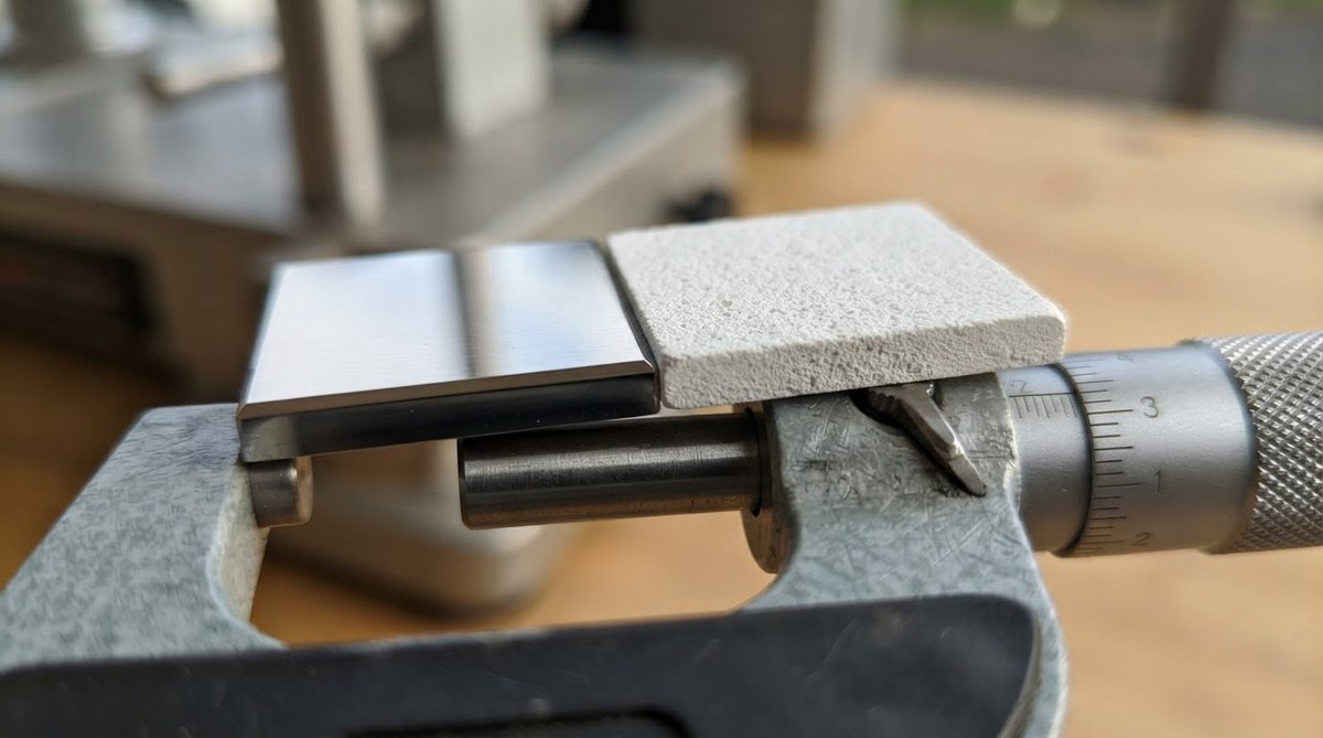
Substrate manufacturers such as CoorsTek, Kyocera, and Maruwa publish catalogs of standard 96% alumina thicknesses. The table below lists the sizes you can typically order without custom processing.
| Thickness (mm) | Thickness (inches) | Typical Use | Relative Availability |
|---|---|---|---|
| 0.25 | 0.010 | Thin-film circuits, RF hybrids | Standard from major suppliers |
| 0.381 | 0.015 | Thick-film hybrids, LED substrates | Widely stocked |
| 0.50 | 0.020 | Power electronics, sensor substrates | Standard |
| 0.635 | 0.025 | General-purpose thick-film, DPC | Most common; lowest cost per unit |
| 1.0 | 0.040 | High-voltage isolation, mechanical carriers | Widely stocked |
| 1.27 | 0.050 | Power modules, structural substrates | Standard |
| 2.0 | 0.079 | High-voltage standoff, heater plates | Available; longer lead time |
Typical values for commercially available material, for comparison only. Confirm against the datasheet for your specific grade.
If your design calls for a thickness not listed here, most manufacturers can produce custom sizes in 0.05 mm increments, though minimum order quantities increase and lead times typically add 2–4 weeks.
Dimensional Tolerances by Finishing Method
Tolerance depends heavily on how the substrate is finished after sintering. As-fired alumina has rougher surfaces and wider dimensional spread. Lapping and polishing tighten both thickness tolerance and surface roughness, at added cost. Selecting the right finish is just as important as selecting among the alumina 96% Al2O3 thickness options themselves.
| Finish | Thickness Tolerance | Surface Roughness (Ra) | Source |
|---|---|---|---|
| As-fired | ±0.05 mm (±0.002″) | 0.5–1.0 µm | CoorsTek ADS-96R datasheet |
| Lapped (one side) | ±0.025 mm (±0.001″) | 0.2–0.5 µm | CoorsTek ADS-96R datasheet |
| Polished (both sides) | ±0.01 mm (±0.0004″) | ≤0.05 µm | Kyocera A-493 datasheet |
Typical values for commercially available material, for comparison only. Confirm against the datasheet for your specific grade.
For thin-film metallization (sputtered or evaporated layers), you generally need a polished surface with Ra below 0.1 µm. Thick-film screen printing works fine on as-fired or lapped substrates. Specifying tighter tolerances than your process actually requires adds cost without benefit.
How Alumina 96% Al2O3 Thickness Affects Thermal Performance
Thermal resistance through the substrate scales linearly with thickness. For 96% alumina with a thermal conductivity of 24–28 W/mK (at 20 °C, per CoorsTek ADS-96R), you can estimate conduction resistance with:
Rth = t / (k × A)
where t is thickness (m), k is thermal conductivity (W/mK), and A is the heat-spreading area (m²).
Worked Example
A 10 mm × 10 mm die mounted on a 96% alumina substrate dissipating 5 W:
- At 0.635 mm thickness: Rth = 0.000635 / (25 × 0.0001) = 0.254 °C/W → ΔT = 1.27 °C
- At 0.25 mm thickness: Rth = 0.000250 / (25 × 0.0001) = 0.100 °C/W → ΔT = 0.50 °C
- At 1.0 mm thickness: Rth = 0.001000 / (25 × 0.0001) = 0.400 °C/W → ΔT = 2.00 °C
Enter your substrate area, thickness, and dissipated power below to estimate junction temperature rise for any of the standard alumina 96% Al2O3 thickness options.
In most designs the substrate itself is not the dominant thermal resistance (the die-attach layer and heat-sink interface usually dominate), but in thermally constrained packages, going from 0.635 mm to 0.25 mm saves roughly 0.15 °C/W per cm² of die area. If your thermal budget is tighter still, consider aluminum nitride substrate thickness options, where conductivity reaches 170–200 W/mK.
How Thickness Affects Mechanical Strength
Flexural strength of 96% alumina is typically 340–380 MPa (per ASTM C1161, 3-point bend). The load a substrate can survive before fracture scales with the square of its thickness. Halving the thickness cuts the load capacity to roughly one quarter.
For substrates below 0.381 mm, handling breakage during assembly becomes a real concern. Automated pick-and-place with vacuum tooling is strongly recommended. If your substrate must survive significant mechanical stress—clamping, vibration, or thermal cycling with a CTE-mismatched baseplate—stay at 0.635 mm or thicker unless you have validated the design with finite-element analysis.
Thickness and Dielectric Isolation
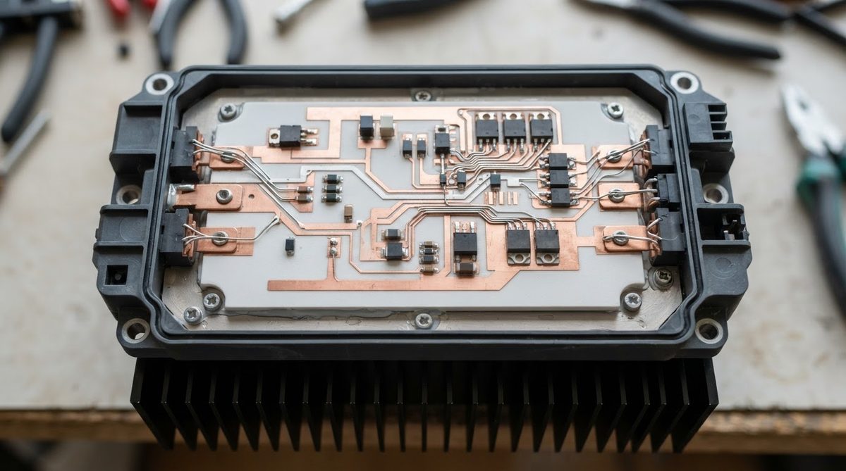
96% alumina has a dielectric strength of approximately 10–15 kV/mm (per IEC 60672-3). A 0.635 mm substrate provides roughly 6.4–9.5 kV of breakdown voltage. For high-voltage power modules requiring isolation above 5 kV, 1.0 mm is a common choice, providing a comfortable margin even after accounting for edge effects and surface contamination.
If your application involves purity-sensitive circuits or higher dielectric requirements, the properties of 99.6% alumina offer lower loss tangent and slightly higher dielectric strength at a premium price.
When Not to Use 96% Alumina
96% alumina is the workhorse ceramic substrate, but it is not always the right pick:
- Thermal conductivity above 30 W/mK needed: Switch to AlN (170–200 W/mK) or consider a DBC/AMB approach on AlN or Si₃N₄.
- Extreme thermal cycling (ΔT > 150 °C, >3,000 cycles): Si₃N₄ substrates offer far higher fracture toughness (6–7 MPa·√m vs. 3.5–4.0 for 96% Al₂O₃). See silicon nitride substrate datasheets for comparison.
- Cost is the primary driver and thermal/frequency demands are low: FR-4 or metal-core PCB will be 5–10× cheaper per unit area.
- Very large panel sizes (>150 mm): Ceramic substrates are limited in panel size compared to organic laminates. Tiling or multi-up panelization adds cost.
To compare substrate materials side by side, the guide on types of ceramic substrates covers the full range from alumina through AlN and Si₃N₄.
Choosing the Right Thickness: A Decision Checklist
- Calculate your thermal budget. Use the Rth formula above. If the substrate contributes less than 10% of total thermal resistance, thickness choice is driven by other factors.
- Check your isolation voltage requirement. Divide the required withstand voltage by 10 kV/mm to get the minimum thickness, then add margin for edge effects.
- Assess mechanical handling. Substrates below 0.381 mm need careful fixturing. If you are hand-placing parts, consider 0.50 mm or thicker.
- Confirm availability. Standard thicknesses (0.381, 0.635, 1.0 mm) ship faster and cost less. Custom thicknesses add lead time.
- Specify only the tolerance you need. As-fired is cheapest. Pay for lapping or polishing only if your metallization process demands it.
Frequently Asked Questions
What is the thinnest 96% alumina substrate available?
Standard catalogs from major suppliers list 0.25 mm (0.010″) as the thinnest 96% alumina option. Thinner substrates (down to 0.127 mm) exist but are typically produced in 99.6% alumina or AlN for thin substrate applications where higher purity improves yield during polishing and metallization.
Can I get a custom thickness between standard sizes?
Yes. Most manufacturers can produce custom thicknesses in increments of approximately 0.05 mm. Expect higher MOQs (often 100+ pieces) and 2–4 weeks of additional lead time compared to stocked sizes.
Does thickness affect the CTE of 96% alumina?
No. The coefficient of thermal expansion of 96% alumina is a bulk material property, approximately 7.1–7.4 ppm/°C from 25–300 °C (per CoorsTek ADS-96R datasheet). It does not change with substrate thickness.
Should I choose lapped or polished substrates?
Lapped substrates (Ra 0.2–0.5 µm) are sufficient for thick-film and DPC metallization. Polished substrates (Ra ≤.05 µm) are needed for thin-film sputtering or when die-attach bond-line thickness must be tightly controlled. Polishing roughly doubles the substrate cost compared to as-fired.
How do alumina 96% Al2O3 thickness options compare to AlN?
AlN substrates are available in a similar range (0.25–2.0 mm), but the most common AlN thickness is 0.635 mm. The key difference is thermal conductivity: AlN at 170–200 W/mK means a thicker AlN substrate can match the thermal resistance of a much thinner alumina substrate. Detailed options are covered in the AlN thickness and tolerance guide.