When engineers evaluate HTCC vs LTCC for a multilayer ceramic substrate, the core trade-off is straightforward: HTCC (High-Temperature Co-fired Ceramic) fires at 1 500–1 800 °C and requires refractory metallization (tungsten or molybdenum-manganese), which limits conductor conductivity. LTCC (Low-Temperature Co-fired Ceramic) fires at 800–900 °C and uses silver, gold, or copper conductors with roughly 10× lower resistivity. HTCC produces a denser, stronger, and more thermally conductive substrate, while LTCC offers tighter line widths, better RF performance, and easier integration of passive components.
Key Takeaways
- HTCC substrates reach flexural strengths of 300–400 MPa (per ASTM C1161) versus 200–320 MPa for typical LTCC tapes, making HTCC better suited to high-vibration environments.
- LTCC conductor resistivity (silver: ~1.6 µΩ·cm) is roughly one-tenth that of HTCC tungsten (~5.5 µΩ·cm), giving LTCC a clear advantage in RF and high-frequency circuits above 1 GHz.
- HTCC thermal conductivity is 20–28 W/m·K for 92–96 % alumina bodies, while LTCC glass-ceramic tapes typically range from 2–5 W/m·K (per Kyocera and CeramTec datasheets).
- LTCC allows embedded passives—resistors, capacitors, inductors—inside the ceramic stack, reducing board area by 30–50 % in RF front-end modules.
- Both processes support 40+ layer counts, but LTCC tooling costs less per design iteration because green tape is easier to punch and screen-print before firing.
What Are HTCC and LTCC?
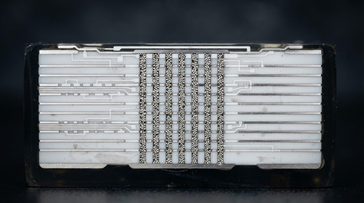
HTCC is a process in which alumina-based ceramic green tape (typically 92–96 % Al₂O₃) is printed with refractory metal paste, stacked, laminated, and co-fired in a reducing atmosphere above 1 500 °C. The high sintering temperature produces a dense, hermetic body with excellent mechanical and thermal properties. Packages for military hybrids, hermetic sensor housings, and high-power LED submounts are common HTCC applications. For a broader overview of how co-fired methods fit alongside DBC, DPC, and thick film, see the ceramic PCB manufacturing process guide.
LTCC is a process in which glass-ceramic green tape (alumina + borosilicate glass, or proprietary compositions such as DuPont 951 or Ferro A6M) is printed with low-resistivity metal paste, stacked, and co-fired at 800–900 °C in air or nitrogen. The lower firing temperature is what permits silver and gold conductors. LTCC dominates in RF modules, automotive radar, and miniaturised sensor packages where embedded passives and fine lines matter more than raw thermal conductivity.
HTCC vs LTCC: Head-to-Head Specification Comparison
| Parameter | HTCC | LTCC | Unit | Condition / Source |
|---|---|---|---|---|
| Firing temperature | 1 500–1 800 | 800–900 | °C | Peak sinter, air/reducing |
| Base ceramic | 92–96 % Al₂O₃ | Glass-ceramic (Al₂O₃ + glass) | — | Kyocera / DuPont datasheets |
| Conductor metals | W, Mo, Mo-Mn | Ag, Au, Cu | — | — |
| Conductor resistivity | 5.0–5.6 | 1.6–2.5 (Ag–Cu) | µΩ·cm | 20 °C |
| Dielectric constant (εr) | 9.0–9.9 | 5.0–7.8 | — | 1 MHz, per CeramTec / Ferro |
| Loss tangent (tan δ) | 0.0001–0.0004 | 0.001–0.003 | — | 1 MHz |
| Thermal conductivity | 20–28 | 2–5 | W/m·K | 20 °C, ASTM E1461 |
| Flexural strength | 300–400 | 200–320 | MPa | ASTM C1161 |
| CTE | 6.5–7.2 | 5.0–7.0 | ppm/°C | 25–300 °C |
| Min line / space | 100 / 100 | 50 / 50 (production); 25 / 25 (advanced) | µm | Screen print / photo-patterned |
| Layer count | Up to 50+ | Up to 60+ | — | — |
| Hermeticity | Yes (He leak < 1 × 10⁻⁸ atm·cc/s) | Yes (with proper via design) | — | MIL-STD-883, Method 1014 |
Typical values for commercially available material, for comparison only. Confirm against the datasheet for your specific grade.
Thermal Performance: Where HTCC Wins
HTCC’s alumina body conducts heat 4–10× better than LTCC glass-ceramic. For a 1 mm-thick substrate dissipating 10 W over a 10 × 10 mm footprint, the steady-state thermal resistance through the ceramic alone is:
R_th = t / (k × A)
HTCC (k = 25 W/m·K): R_th = 0.001 / (25 × 0.0001) = 0.40 °C/W
LTCC (k = 3 W/m·K): R_th = 0.001 / (3 × 0.0001) = 3.33 °C/W
At 10 W, that difference is 29.3 °C of additional temperature rise through the LTCC substrate. For high-power devices, that margin matters. LTCC designers compensate with thermal vias—arrays of silver-filled vias under the die pad—bringing effective through-plane conductivity up to 10–15 W/m·K, but this consumes routing real estate and adds process steps.
Enter your substrate area, thickness, and dissipated power below to estimate junction temperature rise for either process.
If your thermal budget is tight and the die dissipates more than a few watts, HTCC or a post-fired metallization process like AlN or Si₃N₄ with DBC/AMB is usually the better path. The broader question of ceramic thermal management strategies covers heat-spreading options beyond co-fired substrates.
RF and High-Frequency Performance: Where LTCC Wins
Silver conductors in LTCC have a skin-depth resistivity advantage that grows with frequency. At 10 GHz, conductor loss dominates total insertion loss in a microstrip line. A 50 Ω line on LTCC (εr ≈ 7, Ag conductor) shows roughly 0.02–0.04 dB/mm loss, versus 0.06–0.10 dB/mm for the same geometry on HTCC with tungsten, per published Kyocera application notes.
LTCC’s lower dielectric constant (5.0–7.8 versus 9.0–9.9) also means wider 50 Ω traces for a given substrate thickness, which eases fabrication tolerances. And because LTCC tapes are available in multiple εr values, designers can mix high-k and low-k layers in a single stack—high-k for embedded capacitors, low-k for transmission lines. This is a key reason the HTCC vs LTCC decision tilts toward LTCC for anything above roughly 5 GHz.
Automotive 77 GHz radar modules, 5G mmWave antenna-in-package (AiP) designs, and UWB sensor modules almost universally use LTCC for these reasons. For a broader look at metallization choices affecting RF loss, see the silver vs copper metallization comparison.
Embedded Passives and Integration Density
LTCC’s real differentiator is the ability to screen-print resistors, capacitors, and inductors directly into internal layers. A buried capacitor using a high-k dielectric layer (εr 50–200) replaces a discrete 0201 MLCC. A buried spiral inductor replaces a surface-mount chip inductor. In volume RF front-end modules, this integration can shrink board area by 30–50 % and eliminate hundreds of solder joints per module.
HTCC can embed some passive structures, but the refractory metal paste has higher sheet resistance (~10–20 mΩ/sq for W versus ~2–3 mΩ/sq for Ag), limiting inductor Q-factors and resistor precision. Most HTCC designs rely on surface-mount passives instead.
Cost Drivers and Typical Price Ranges
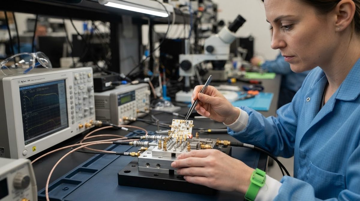
Both processes share a similar workflow—tape casting, via punching, screen printing, lamination, firing—but their cost structures diverge in three areas:
- Metal paste cost. Gold paste for LTCC is expensive, but silver paste is cheap. Tungsten paste for HTCC is moderate. In high-volume LTCC production, silver-based builds are often cheaper per layer than HTCC tungsten builds.
- Firing energy. HTCC kilns run 600–900 °C hotter and require reducing-atmosphere gas (H₂/N₂ mix). Energy cost per firing cycle is roughly 2–3× that of LTCC air-fired kilns.
- Tooling iteration. LTCC green tape is softer and easier to punch and laminate, making prototype turns faster. HTCC’s higher shrinkage tolerance (±0.5–1.0 % versus ±0.1–0.3 % for constrained-sintered LTCC) can require more design iterations to hit tight feature placement.
For simple hermetic packages (≤6 layers, no embedded passives), HTCC is often competitive or cheaper because alumina tape is less expensive than proprietary LTCC tapes. For complex multilayer RF modules (10–40 layers with embedded passives), LTCC usually wins on total cost per function. Comparing ceramic substrates against metal-core alternatives is a separate question covered in the ceramic vs MCPCB star-board comparison.
When NOT to Use Co-fired Ceramic (HTCC or LTCC)
Neither HTCC nor LTCC is the right choice if:
- Your board is larger than ~150 × 150 mm. Co-fired shrinkage control becomes difficult at large panel sizes. Post-fired processes (DPC, thick film, DBC) on pre-sintered substrates handle larger formats more economically.
- You need thick copper (≥ 100 µm) for high-current busbars. Co-fired conductors are typically 8–25 µm thick. For heavy copper, look at DBC or AMB on alumina or AlN. The thick film versus thin film guide covers post-fired metallization options.
- Your thermal load exceeds what the substrate can handle and you cannot add thermal vias. If you need >150 W/m·K through-plane conductivity, AlN with DBC or AMB is the standard answer.
- Cost is the primary constraint and the application does not require hermeticity, high temperature, or RF performance. FR-4 or standard MCPCB will be 5–20× cheaper. See the ceramic vs FR-4 comparison for the breakpoints.
Decision Checklist: HTCC vs LTCC
Run through these five questions. If most answers point one way, that is probably your process.
- Is through-substrate thermal conductivity > 10 W/m·K critical? → HTCC.
- Does the design operate above 5 GHz with tight insertion-loss budgets? → LTCC.
- Do you need embedded passives to shrink module area? → LTCC.
- Is the package primarily a hermetic enclosure with simple routing (≤6 layers)? → HTCC is simpler and often cheaper.
- Must the substrate survive sustained temperatures above 800 °C in service? → HTCC. LTCC glass phases may soften above 700–800 °C depending on composition.
Frequently Asked Questions
Can LTCC handle high operating temperatures?
LTCC substrates are typically rated for continuous use up to 500–700 °C, depending on the tape system and metallization. Above that range, the glass phase in LTCC can begin to soften. HTCC alumina bodies remain stable well above 1 000 °C. For extreme-temperature sensing or exhaust-gas applications, HTCC is the safer choice.
Is LTCC hermetic enough for military and space applications?
Yes. Properly designed LTCC packages routinely meet MIL-STD-883 Method 1014 hermeticity requirements (He leak rate < 1 × 10⁻⁸ atm·cc/s). Via density and seal-ring design are the critical factors. Both HTCC and LTCC are qualified for space-grade packaging.
Can I mix HTCC and LTCC in the same assembly?
You can mount an LTCC module onto an HTCC base or carrier using solder or epoxy attach. The CTE values are close enough (5–7 ppm/°C for both) that thermal cycling reliability is generally acceptable. This hybrid approach is common in military TR modules where the HTCC base provides thermal spreading and the LTCC module handles RF signal routing.
What is the typical lead time for HTCC versus LTCC prototypes?
LTCC prototypes typically take 3–6 weeks from design release to fired parts, because green tape processing is faster and firing cycles are shorter. HTCC prototypes often require 5–8 weeks due to longer firing profiles and the additional step of nickel/gold plating over the refractory metallization to enable soldering.
Which process has better dimensional tolerance after firing?
LTCC achieves tighter post-fire tolerances, especially with constrained sintering techniques (zero-shrinkage LTCC), where X-Y shrinkage can be held to ±0.1 %. Free-sintered HTCC typically holds ±0.5–1.0 % X-Y shrinkage. If your design has tight via-to-pad registration requirements, LTCC or constrained LTCC is preferred.
Next Step
If you have narrowed your HTCC vs LTCC process choice and need to compare ceramic substrates across other parameters, the ceramic PCB materials overview covers alumina, AlN, Si₃N₄, and glass-ceramic options side by side. When you are ready to get pricing on a specific design, upload your files for an instant quote.