Is ceramic PCB better than FR4? Yes—but only when your design is thermally, thermally-at-frequency, or high-temperature constrained. Ceramic substrates deliver 24–200 W/mK thermal conductivity versus FR-4’s 0.3–0.4 W/mK, survive continuous operation above 300 °C where FR-4 delaminates past its 130–180 °C Tg, and offer dielectric losses 10–100× lower at GHz frequencies. FR-4 wins on cost (5–20× cheaper per cm²) and mechanical toughness (it bends; ceramic shatters). The right choice depends entirely on which of those parameters your design cannot compromise on.
Head-to-Head Specification Table: Is Ceramic PCB Better Than FR4?
| Parameter | FR-4 (Standard) | Al₂O₃ 96% | AlN | Unit | Condition / Source |
|---|---|---|---|---|---|
| Thermal conductivity | 0.3–0.4 | 24–28 | 170–200 | W/mK | 20 °C; CoorsTek / Maruwa datasheets |
| Glass transition (Tg) or max continuous temp | 130–180 | ~1 600 (no Tg) | ~1 000 (no Tg) | °C | IPC-TM-650 2.4.25 (FR-4); ceramic has no polymeric phase |
| CTE (x-y) | 14–17 | 6.5–7.2 | 4.3–4.6 | ppm/°C | 20–300 °C; Kyocera A-493 datasheet |
| Dielectric constant (εr) | 4.2–4.8 | 9.0–9.8 | 8.5–9.0 | — | 1 MHz; manufacturer TDS |
| Loss tangent (tan δ) | 0.017–0.025 | 0.0001–0.0004 | 0.0005–0.002 | — | 1 GHz; Maruwa / Rogers published data |
| Flexural strength | 415–550 | 300–380 | 300–350 | MPa | ASTM C1161 (ceramic); IPC-TM-650 (FR-4) |
| Relative cost per cm² | 1× | 5–10× | 15–20× | — | Typical 2-layer, 50 × 50 mm, qty 100 |
Typical values for commercially available material, for comparison only. Confirm against the datasheet for your specific grade.
Where Ceramic Wins Over FR-4
Thermal management
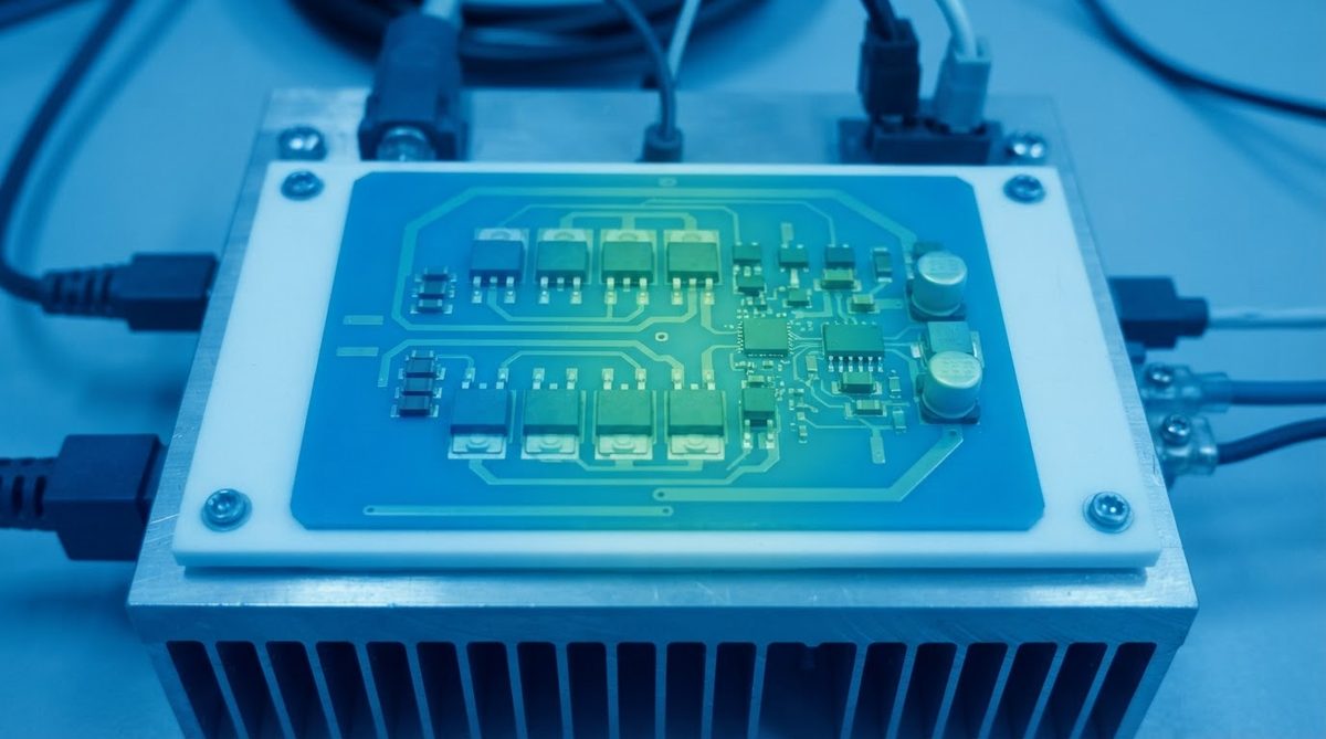
FR-4’s thermal conductivity is roughly 0.3 W/mK. A 96% alumina substrate delivers 24–28 W/mK—about 70–90× higher. For a 10 W power device on a 25 × 25 mm substrate that is 0.635 mm thick, the conduction thermal resistance through the substrate drops from approximately 4.2 °C/W (FR-4) to about 0.04 °C/W (Al₂O₃ 96%). That difference alone can eliminate a heatsink or fan. For LED star boards comparing ceramic and MCPCB, the substrate thermal path often dominates the total junction-to-ambient resistance. When asking is ceramic PCB better than FR4 for power electronics, the thermal numbers answer the question decisively.
High-temperature operation
FR-4 is an epoxy-glass laminate. Above its Tg (130–180 °C), the resin softens, CTE spikes, and delamination risk climbs. Ceramic substrates have no polymeric binder. A ceramic PCB based on alumina can operate continuously at 300–400 °C with metallization intact, and the substrate itself survives beyond 1 000 °C. This matters for downhole sensors, exhaust-gas probes, and jet-engine proximity electronics.
RF and microwave performance
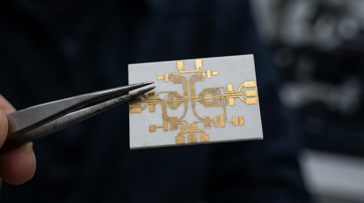
At 10 GHz, FR-4’s loss tangent of ~0.02 eats signal. Alumina’s tan δ of 0.0002 at 10 GHz makes it a standard choice for filters, couplers, and antenna feed networks. The higher εr (≈9.5) does shrink wavelength, so traces are narrower—an advantage for miniaturisation but a tolerance challenge for impedance control. For RF front-ends above 2 GHz, the question of whether ceramic PCB is better than FR4 has a clear answer: ceramic preserves signal integrity that FR-4 simply cannot.
Enter your substrate material, thickness, and dissipated power below to see how junction temperature rise compares between ceramic and FR-4 for your specific layout.
Where FR-4 Wins Over Ceramic
Cost
A standard 4-layer FR-4 board in quantity 1 000 might cost $0.02–0.05/cm². The same footprint in 96% alumina with thick-film metallization runs $0.20–0.50/cm². AlN pushes that to $0.50–1.00/cm². If your thermal budget closes with FR-4 and thermal vias, the cost argument is overwhelming. For designs where thermal margins are comfortable, is ceramic PCB better than FR4? No—FR-4 is the rational choice.
Mechanical toughness and panel size
FR-4 flexes. You can route, V-score, and panelise it in 18 × 24 inch sheets. Ceramic substrates are brittle (fracture toughness ~3–4 MPa·√m for alumina vs. effectively ductile behaviour in FR-4) and limited to smaller panels—typically 100–150 mm per side. Drop a ceramic board on concrete and it cracks. Drop FR-4 and you pick it up. For consumer products with mechanical shock requirements, this matters. The weight difference between ceramic and FR-4 also affects portable designs: alumina is roughly 2× denser than FR-4.
Design ecosystem
Every fab house, assembler, and EDA tool supports FR-4 out of the box. Ceramic PCBs require matched-CTE solder alloys, specific reflow profiles, and suppliers experienced with ceramic handling. Assembly yield can be lower if your contract manufacturer is unfamiliar with the material.
Worked Example: Does Your Board Need Ceramic?
Suppose you have a GaN half-bridge dissipating 15 W on a 30 × 30 mm footprint. The maximum case-to-board thermal resistance you can tolerate is 0.5 °C/W.
FR-4 (1.6 mm thick): Rth = t / (k × A) = 0.0016 / (0.35 × 0.0009) = ~5.1 °C/W. Fails by 10×.
Al₂O₃ 96% (0.635 mm thick): Rth = 0.000635 / (25 × 0.0009) = ~0.028 °C/W. Passes with margin.
In this case, ceramic is not a luxury—it is the only substrate that closes the thermal loop without adding a separate copper spreader. This worked example shows concretely when ceramic PCB is better than FR4: whenever the thermal resistance budget cannot be met by organic laminates.
When Not to Use Ceramic
Choose FR-4 (or a metal-core PCB) when:
- Your hottest component stays below 100 °C junction temperature with standard thermal vias and a heatsink.
- The board is larger than ~120 × 120 mm and multilayer (≥4 layers). Ceramic multilayer is possible via LTCC or HTCC but cost escalates fast. Refer to the ceramic PCB glossary for details on those processes.
- The product will experience repeated mechanical shock or flex—handheld devices, automotive body-mounted sensors with high vibration and no potting.
- Your production volume exceeds 50 000 units/year and thermal requirements are moderate. FR-4 with copper-coin inserts may close the gap at a fraction of the cost.
Frequently Asked Questions
Is ceramic PCB better than FR4 for every application?
No. Ceramic is better only when thermal conductivity, operating temperature, or high-frequency loss tangent are design-critical. For general digital logic, connectors, and low-power analog, FR-4 is cheaper, tougher, and easier to source.
Can I use standard SMT assembly on a ceramic PCB?
Yes. Standard reflow soldering works on ceramic substrates with appropriate solder paste (typically SAC305 or AuSn for high-reliability). The main difference is that ceramic’s low CTE (6–7 ppm/°C for alumina) creates a mismatch with large BGA packages, so underfill or compliant leads may be needed. See soldering to a ceramic PCB for process details.
Does the higher dielectric constant of ceramic cause impedance problems?
It changes impedance, but it does not cause problems if you design for it. A 50 Ω microstrip on alumina (εr ≈ 9.5) is roughly 40% narrower than on FR-4 (εr ≈ 4.4). This is an advantage for miniaturisation but requires tighter trace-width tolerance—typically ±10 µm on thin-film ceramic versus ±25–50 µm on standard FR-4 etching.
How much more does a ceramic PCB cost than FR-4?
Expect 5–10× for 96% alumina and 15–20× for AlN, comparing equivalent board area in prototype quantities (50–100 pcs). The gap narrows slightly at higher volumes but never closes. Material cost, slower processing, and lower panel utilisation all contribute.
Can ceramic PCBs be made as thin as FR-4?
Ceramic substrates are available as thin as 0.1 mm (100 µm), which is thinner than standard FR-4 cores (typically 0.2 mm minimum). Handling fragility increases sharply below 0.25 mm, so fixture design and assembly process matter more than the substrate itself.
Is ceramic PCB RoHS compliant?
Alumina, aluminum nitride, and silicon nitride substrates contain no restricted substances under RoHS. The metallization and surface finish determine compliance—ENIG and OSP finishes are RoHS-compliant; some legacy thick-film pastes contain lead and require exemption or substitution.