When evaluating ceramic PCB silver vs copper metallization, the short answer is that copper delivers roughly 20% higher as-deposited electrical conductivity and far better electromigration resistance, but silver remains the standard for thick-film and LTCC processes where copper’s oxidation during high-temperature firing is impractical. Your choice hinges on process compatibility, operating environment, and cost constraints—not a blanket “one is better” answer.
Key Takeaways
- Bulk electrical resistivity of copper is 1.68 µΩ·cm versus 1.59 µΩ·cm for silver at 20 °C (per CRC Handbook of Chemistry and Physics), but fired thick-film pastes never reach bulk values—expect 2–5× higher.
- Silver is prone to electromigration under DC bias and humidity; copper is not, making copper the safer choice for high-reliability or outdoor designs.
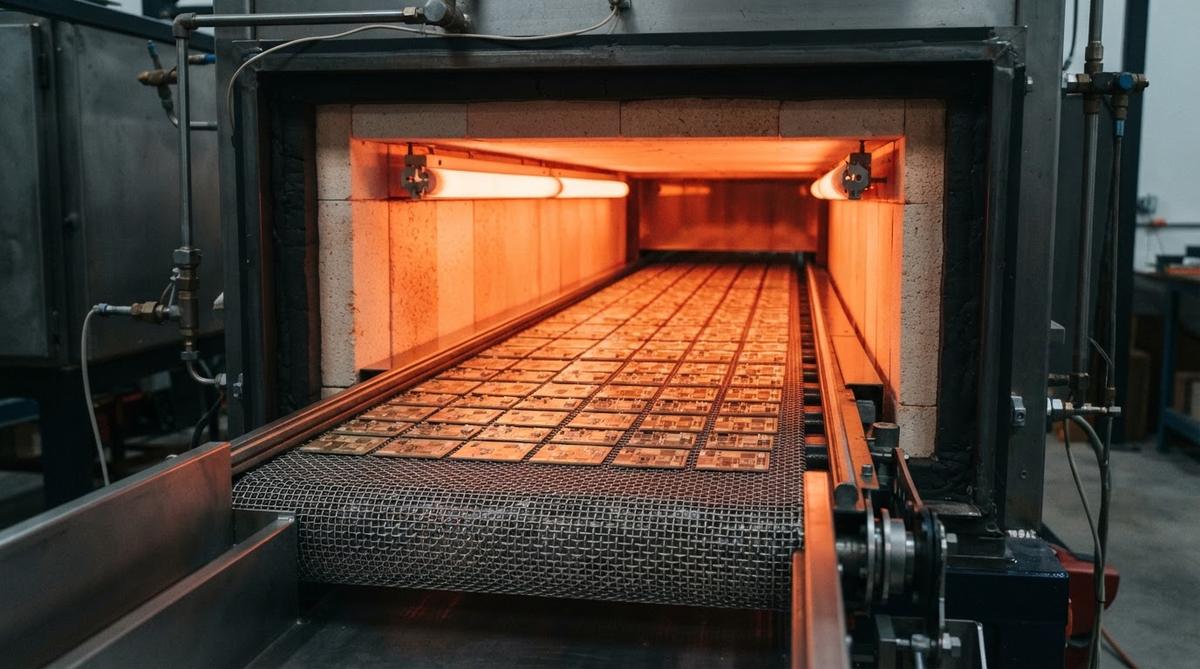
- Silver thick-film paste fires in air at 850 °C; copper paste requires a nitrogen atmosphere to prevent oxidation, adding furnace cost.
- Copper metallization via DPC (direct plated copper) or DBC (direct bond copper) supports trace thicknesses from a few microns to 300 µm+, covering both fine-line RF and high-current power applications.
- Silver spot price (as of mid-2025) is roughly 30–35 USD/troy oz, while copper is under 5 USD/lb—but paste cost per board depends more on layer count and print area than on raw metal price.
Ceramic PCB Silver vs Copper Metallization: Electrical and Thermal Properties
Both metals are excellent conductors, but the gap between their bulk values and their as-deposited values on a ceramic substrate matters more than the textbook numbers.
A thick-film silver conductor fired on 96% alumina typically measures 2.5–5 mΩ/sq for a 10–12 µm print (per DuPont 6142D datasheet). A sputtered-and-plated copper trace on the same substrate, produced by a DPC process, reaches near-bulk resistivity because the copper is deposited in a dense, fully metallic state—typically 1.8–2.2 µΩ·cm.
Thermal conductivity follows the same ranking: copper at 390–400 W/m·K versus silver at 410–430 W/m·K in bulk form. In practice, the substrate’s thermal conductivity (24–28 W/m·K for 96% Al₂O₃) dominates the ceramic thermal management path, so the metallization metal itself rarely determines junction temperature.
| Parameter | Silver (thick-film) | Copper (DPC / plated) | Unit | Condition | Source |
|---|---|---|---|---|---|
| Bulk resistivity | 1.59 | 1.68 | µΩ·cm | 20 °C | CRC Handbook, 97th ed. |
| As-deposited resistivity | 3–8 | 1.8–2.5 | µΩ·cm | Fired / plated, 20 °C | DuPont 6142D; typical DPC process data |
| Thermal conductivity (bulk) | 429 | 398 | W/m·K | 20 °C | CRC Handbook |
| Typical trace thickness | 8–15 | 5–300 | µm | — | Process-dependent |
| Min line/space (practical) | 100 / 100 | 30 / 30 | µm | Screen print vs DPC | Industry typical |
| Electromigration risk | High under DC + humidity | Low | — | 85 °C / 85% RH, 5 V DC | IPC-TM-650 2.6.14.1 |
| Firing atmosphere | Air | Nitrogen (thick-film) / vacuum (DPC sputter) | — | 850 °C peak | Paste manufacturer datasheets |
Typical values for commercially available material, for comparison only. Confirm against the datasheet for your specific grade.
Silver Electromigration: The Hidden Reliability Risk
Silver ions migrate between conductors under the combination of DC voltage, moisture, and closely spaced traces. Dendrites grow from cathode to anode and eventually short the circuit. This failure mode is well-documented in IPC-TM-650, Method 2.6.14.1 (Surface Insulation Resistance). At 85 °C, 85% RH, and 10 V DC bias, silver conductors on alumina can show resistance drops within hundreds of hours if spacing is tight.
For LED boards, sensor substrates, and consumer products that live in sealed enclosures, silver thick-film works fine—the humidity exposure is low and trace spacing is generous. For automotive under-hood modules, outdoor telecom, or implantable medical devices, copper metallization eliminates this failure mode entirely. Understanding this trade-off is central to the ceramic PCB silver vs copper metallization decision for any high-reliability project. If you must use silver in a humid environment, an overglaze or conformal coat is mandatory, and you should still validate with SIR testing per IPC-9201.
Process Compatibility: Which Metallization Fits Which Ceramic Process
The ceramic fabrication process often dictates your metallization metal before any electrical comparison begins. Below is how the ceramic PCB silver vs copper metallization choice maps to each major process family.
Thick-film (screen print and fire)
Silver and silver-palladium pastes dominate thick-film because they fire in air. Copper thick-film pastes exist but require a nitrogen-purged belt furnace, which not every shop runs. Gold is a third option for wire-bondable pads but at much higher cost. If your project uses thick-film on alumina and you want copper, confirm the fab has nitrogen firing capability.
DPC (Direct Plated Copper)
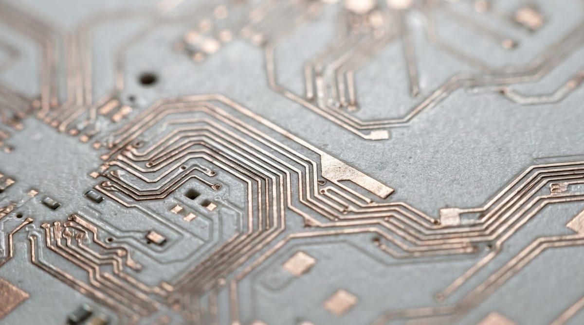
DPC deposits copper by sputtering a Ti/Cu seed layer, then photolithographically patterning and electroplating copper to the target thickness. Silver is not used in DPC. This process yields fine lines (down to 30 µm), tight tolerances, and near-bulk copper conductivity. It suits RF, sensor, and high-density interconnect applications. For a deeper look at how electroplated copper builds up on ceramic, see our ceramic PCB manufacturing process overview.
DBC and AMB
Direct Bond Copper (DBC) bonds a copper foil to the ceramic at the Cu–CuO eutectic (~1065 °C). Active Metal Brazing (AMB) uses a TiAgCu braze to bond copper foil, especially onto AlN or Si₃N₄. Both processes are copper-only; silver has no role here. These methods produce 127–300 µm copper layers for power electronics. For guidance on choosing between them, see the DBC vs AMB selection guide.
LTCC (Low-Temperature Co-fired Ceramic)
LTCC fires at 850–900 °C. Silver and silver-palladium are the standard internal and external conductors. Copper LTCC is possible but requires the entire lamination and firing process to run in a reducing atmosphere, which limits it to specialized fabs. Gold is used for wire-bond pads. If your design is LTCC, plan on silver unless you have a specific reason and a capable supplier.
Worked Example: Sheet Resistance and Trace Width
Suppose you need a 50 Ω RF feedline on a 96% alumina substrate at 2.4 GHz. You care about conductor loss, which scales with sheet resistance. This example illustrates how the ceramic PCB silver vs copper metallization choice affects real performance numbers.
Silver thick-film: 12 µm print, measured sheet resistance 3 mΩ/sq. For a 200 µm wide trace, DC resistance per mm of length = (3 mΩ/sq) / (0.2 mm / 1 sq) ≈ 15 mΩ/mm. At RF, skin effect raises this further.
DPC copper: 10 µm plated copper, sheet resistance ≈ 1.7 mΩ/sq. Same 200 µm trace: DC resistance per mm ≈ 8.5 mΩ/mm—roughly half the loss. And DPC can resolve 50 µm lines, letting you shrink the layout.
For a 10 mm feedline, that difference is 150 mΩ vs 85 mΩ. In a low-noise front end, 65 mΩ of extra loss translates directly into degraded noise figure. This is why most RF ceramic PCB designs above 1 GHz use DPC copper.
Cost Drivers for Silver and Copper on Ceramic
Raw metal cost is a small fraction of the finished board price. The larger cost factors are process setup, atmosphere control, and yield.
- Silver thick-film is the cheapest ceramic metallization process for simple layouts. Screen, fire in air, done. Paste cost per board on a 25 × 25 mm substrate is typically under 0.50 USD.
- Copper thick-film adds nitrogen furnace cost—roughly 10–20% premium over silver thick-film.
- DPC copper requires vacuum sputtering, photolithography, and plating. Higher NRE (tooling, masks) but excellent for fine features. Per-unit cost drops fast at volume.
- DBC / AMB copper uses pre-formed copper foil, so metal cost is predictable. The brazing step and ceramic breakage risk are the main cost drivers.
If you are trying to reduce ceramic PCB cost, switching from DPC to silver thick-film is one lever—but only if your line/space and reliability requirements allow it.
When NOT to Use Silver Metallization
Choose copper over silver when any of these apply:
- The board operates in an uncontrolled humidity environment (outdoor, automotive, marine).
- DC bias exceeds 5 V across traces spaced under 200 µm—electromigration risk is too high.
- You need trace widths below 100 µm. Screen-printed silver cannot resolve them; DPC copper can.
- Current density demands thick copper (>50 µm). Thick-film silver tops out around 15 µm per print pass.
- The application requires long-term insulation resistance stability per IPC-9201 or similar.
When NOT to Use Copper Metallization
Silver or gold is the better choice when:
- Your process is LTCC and the fab does not have nitrogen firing. Most LTCC fabs don’t.
- You need the lowest possible cost on a simple single-layer thick-film circuit with generous spacing.
- Wire bonding directly to the conductor is required and gold or silver-palladium is the standard pad metallurgy for your die attach process.
FAQ
Can silver and copper coexist on the same ceramic board?
Yes, but it is uncommon. Some hybrid designs use silver thick-film for internal LTCC layers and copper plating on external pads. The risk is galvanic corrosion at the interface if moisture is present. Barrier layers (nickel, for example) mitigate this.
Does silver tarnish on a ceramic PCB?
Silver reacts with atmospheric sulfur compounds to form Ag₂S, which increases contact resistance. For soldered joints this is irrelevant because the solder wets through the tarnish layer. For wire-bond pads or exposed contacts, an anti-tarnish finish or gold overplate is standard practice.
Is silver-palladium better than pure silver paste?
Silver-palladium (e.g., Ag/Pd 90/10 or 80/20) resists solder leaching better than pure silver, which matters if components are soldered directly to the conductor. The trade-off is higher resistivity—roughly 5–10 mΩ/sq versus 2.5–5 mΩ/sq for pure silver at similar thickness. Use Ag/Pd when soldering is required; use pure Ag for lower loss.
What surface finishes work over copper on ceramic?
ENIG (electroless nickel / immersion gold), ENEPIG, and electrolytic nickel-gold are all used. OSP (organic solderability preservative) is less common on ceramic than on FR-4 because ceramic boards often sit in inventory longer. The finish choice depends on your assembly process. For prototype cost guidance, see the ceramic PCB prototype cost guide.
Does copper metallization add lead time?
DPC copper adds sputtering, lithography, and plating steps that thick-film silver does not require, so yes—expect 1–2 weeks longer for DPC versus a simple thick-film silver board. DBC and AMB have their own lead times driven by brazing and etching.
Which metallization is better for high-frequency RF?
Copper via DPC. It offers lower conductor loss due to near-bulk resistivity, finer line resolution for impedance-controlled traces, and no electromigration concern. Silver thick-film is acceptable below ~1 GHz where conductor loss is less critical and trace widths are generous. For most engineers weighing ceramic PCB silver vs copper metallization in an RF context, DPC copper is the clear winner above 1 GHz.