For power modules above 100 A or operating at junction temperatures beyond 175 °C, the substrate choice usually narrows to two ceramics: silicon nitride (Si3N4) and aluminum nitride (AlN). AlN wins on raw thermal conductivity (170–200 W/mK vs 70–90 W/mK for Si3N4), but Si3N4 wins on mechanical toughness and thermal-cycling reliability by a wide margin. The right pick depends on whether your design is limited by steady-state heat removal or by thermo-mechanical fatigue life.
Key Takeaways
- AlN substrates conduct heat roughly 2–2.5× better than Si3N4 (170–200 W/mK vs 70–90 W/mK at 25 °C), making them the better choice when thermal resistance is the binding constraint.
- Si3N4 has a fracture toughness of 6–7 MPa·√m, roughly 3× that of AlN (2.5–3.0 MPa·√m per ASTM C1421), which translates directly into longer power-cycling and thermal-cycling life.
- Si3N4 AMB substrates routinely survive >3,000 thermal cycles (–40 °C to +250 °C), while AlN AMB substrates typically fail between 500 and 1,500 cycles under the same profile.
- AlN substrates cost roughly 40–60% less per unit area than Si3N4, so they remain the default for cost-sensitive designs that meet reliability targets.
- SiC and GaN power devices pushing junction temperatures above 200 °C are accelerating the industry shift toward Si3N4 substrates.
Material Properties: Si3N4 vs AlN Side by Side
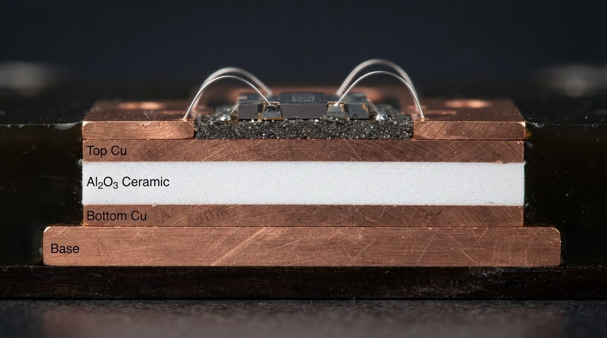
The table below collects the properties that matter most for power-module substrate selection. All values are for commercially available grades used in DBC or AMB metallization.
| Parameter | Si3N4 | AlN | Unit | Condition | Source |
|---|---|---|---|---|---|
| Thermal conductivity | 70–90 | 170–200 | W/mK | 25 °C, ASTM E1461 | Kyocera SN-90 / Maruwa AN-200 datasheets |
| CTE | 2.7–3.0 | 4.5–5.0 | ppm/°C | 20–300 °C | CoorsTek / Kyocera datasheets |
| Flexural strength | 600–900 | 300–400 | MPa | ASTM C1161, 4-pt bend | Kyocera SN-90 / Maruwa AN-200 |
| Fracture toughness (KIC) | 6–7 | 2.5–3.0 | MPa·√m | ASTM C1421 | CeramTec / Kyocera datasheets |
| Dielectric strength | 15–18 | 15–17 | kV/mm | 25 °C, IEC 60672 | Kyocera / Maruwa datasheets |
| Density | 3.2 | 3.26 | g/cm³ | — | CoorsTek datasheets |
| Typical substrate thickness | 0.25–0.32 | 0.38–0.635 | mm | — | Industry standard |
| Relative cost (per cm²) | 1.0× | 0.4–0.6× | — | Volume pricing, 2024 | Industry estimates |
Typical values for commercially available material, for comparison only. Confirm against the datasheet for your specific grade.
Two numbers dominate the decision. Thermal conductivity favors AlN. Fracture toughness favors Si3N4. Everything else flows from that split.
Thermal Performance: How Much Does 2× Conductivity Actually Matter?
AlN’s higher thermal conductivity gives it a lower substrate thermal resistance (Rth,sub). But the substrate is only one layer in the thermal stack. A worked example shows the real impact.
Worked Example: Thermal Resistance Through the Substrate
Consider a 10 mm × 10 mm die on a 0.32 mm substrate, no spreading, one-dimensional heat flow:
Rth,sub = t / (k × A)
For AlN (k = 180 W/mK):
Rth = 0.00032 / (180 × 0.0001) = 0.0178 °C/W
For Si3N4 (k = 90 W/mK):
Rth = 0.00032 / (90 × 0.0001) = 0.0356 °C/W
The difference is 0.018 °C/W. At 500 W dissipation, that adds 9 °C to the junction temperature. In a full module stack (die attach + substrate + base plate + TIM + heatsink), the total Rth,j-a might be 0.15–0.25 °C/W. The substrate accounts for roughly 10–15% of the total. So the AlN-vs-Si3N4 difference in this example shifts junction temperature by about 5–10 °C at 500 W.
That gap matters when you are within 10 °C of a thermal limit. If your design has 30 °C of margin, it usually does not justify the reliability penalty of choosing AlN over Si3N4. For a deeper look at how AlN compares to alumina on thermal and cost grounds, see our dedicated comparison.
Mechanical Reliability: Why Toughness Beats Conductivity in Many Designs
Power modules fail at solder joints, wire bonds, and substrate cracks. The substrate crack mode is driven by CTE mismatch stress during thermal cycling. Copper (CTE ~17 ppm/°C) bonded to a ceramic (CTE 3–5 ppm/°C) generates shear and tensile stress at the copper-ceramic interface every time the module heats and cools.
Si3N4’s fracture toughness of 6–7 MPa·√m means it can absorb more strain energy before a crack propagates. AlN, at 2.5–3.0 MPa·√m, is roughly as brittle as 96% alumina. In practice, this means:
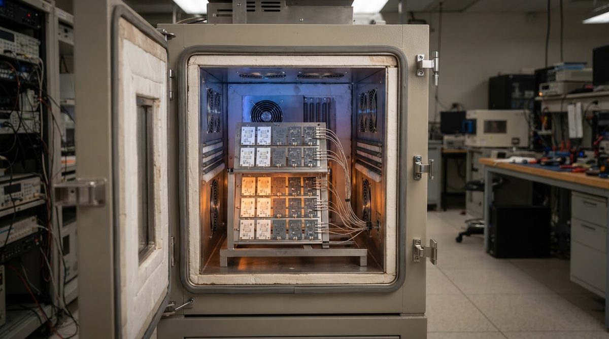
- Si3N4 AMB substrates with 0.3 mm copper routinely survive >3,000 cycles at –40 °C / +250 °C (per Heraeus, Kyocera published reliability data).
- AlN AMB substrates with the same copper thickness typically crack between 500 and 1,500 cycles under the same profile.
- Si3N4 allows thicker copper (up to 0.8 mm per side on AMB) without substrate cracking, which reduces I²R losses in high-current paths.
For automotive traction inverters, industrial drives, and railway converters where the module must survive 10,000+ active power cycles, Si3N4 is the default. The substrate costs more, but the module lasts longer, and field failures cost far more than substrate material. If you are evaluating DBC versus AMB metallization for either material, the bonding process also influences crack initiation.
CTE Mismatch: Si3N4’s Hidden Advantage with SiC and GaN Dies
SiC has a CTE of approximately 4.0 ppm/°C. Si3N4’s CTE of 2.7–3.0 ppm/°C is closer to SiC than AlN’s 4.5–5.0 ppm/°C. While AlN’s CTE is closer in absolute value, the stress at the die-attach interface depends on the full thermal stack, including copper thickness and solder creep. In practice, the higher toughness of Si3N4 matters more than the CTE delta alone.
GaN-on-Si devices inherit silicon’s CTE (~2.6 ppm/°C), which aligns well with Si3N4. As wide-bandgap devices push junction temperatures above 200 °C, the thermal-cycling swing increases, and Si3N4’s toughness advantage becomes even more decisive.
Cost Comparison: What You Actually Pay
Si3N4 substrates cost roughly 1.5–2.5× more than AlN substrates of the same footprint. The gap comes from raw material cost (silicon nitride powder is more expensive) and sintering difficulty (Si3N4 requires higher temperatures and longer soak times, often with gas-pressure sintering).
| Cost Factor | Si3N4 | AlN | Notes |
|---|---|---|---|
| Raw substrate (per cm²) | $0.80–$1.50 | $0.35–$0.70 | 0.32 mm, volume pricing, 2024 estimates |
| AMB metallization | Similar | Similar | Same process; Si3N4 needs slightly different brazing alloy |
| Thinner substrate option | 0.25 mm standard | 0.38 mm minimum typical | Thinner Si3N4 saves material and thermal resistance |
| Qualification testing | Higher pass rate | More rejects at cycling | Yield difference partially offsets substrate cost |
Indicative pricing for comparison only. Request quotes for your specific geometry and volume.
A common mistake is comparing substrate cost alone. If your AlN module fails qualification thermal cycling and you must redesign with thinner copper or derate the power, the “cheaper” substrate ends up costing more in engineering time and lost schedule. For a broader view of ceramic PCB cost versus MCPCB, see our cost comparison.
Metallization Compatibility
Both Si3N4 and AlN work with DBC (direct bond copper) and AMB (active metal brazing). However, the practical picture differs:
- DBC on AlN is well established. The aluminum nitride surface oxidizes to form a thin Al₂O₃ layer that enables the copper-oxide eutectic bond. DBC on Si3N4 is possible but less common; the silicon nitride surface does not form a native oxide as readily, so process control is tighter.
- AMB on Si3N4 is the dominant combination for high-reliability modules. The braze alloy (typically Ag-Cu-Ti) wets Si3N4 well, and the resulting bond is strong enough to support 0.5–0.8 mm copper without delamination.
- AMB on AlN also works, but the reliability advantage of AMB is partially wasted if the substrate itself cracks before the braze joint fails.
If you are comparing AMB versus DPC processes, note that DPC (direct plated copper) is typically used on alumina and AlN for lower-current applications, not on Si3N4.
When to Choose AlN Over Si3N4
AlN is the right substrate when:
- Steady-state thermal resistance is the binding constraint, and thermal cycling requirements are moderate (<500 cycles, ΔT <150 °C).
- The module operates in a controlled environment (telecom, medical imaging, industrial laser) without extreme thermal transients.
- Cost per unit is critical and the reliability target can be met with AlN.
- You need a substrate thicker than 0.5 mm for voltage isolation, where AlN’s higher conductivity compensates for the added thickness.
When to Choose Si3N4 Over AlN
Si3N4 is the right substrate when:
- The module must survive >1,000 thermal cycles with ΔT >200 °C (automotive, traction, aerospace).
- You need thick copper (>0.3 mm) for high-current busbars without risking substrate cracking.
- SiC or GaN dies operate at junction temperatures above 200 °C.
- Field replacement cost is high (undersea, aerospace, remote installations), making substrate reliability worth the premium.
When Not to Use Either
If your power dissipation is under 50 W and thermal cycling is mild, 96% alumina (Al₂O₃) at 24–28 W/mK is adequate and costs a fraction of either AlN or Si3N4. For modules below 20 W, an insulated metal substrate (MCPCB) may be sufficient. And for RF or mixed-signal boards where thermal conductivity is secondary to dielectric loss, HTCC versus LTCC is a more relevant comparison than Si3N4 vs AlN.
Neither Si3N4 nor AlN is compatible with LTCC or HTCC co-firing processes. Both are used as sintered substrates with post-fire metallization (DBC, AMB, or thin film). If your design requires embedded passives or multilayer routing, LTCC on alumina or glass-ceramic is the correct path.
FAQ
Can Si3N4 substrates be made as thin as AlN?
Yes. Si3N4 substrates are commercially available at 0.25 mm thickness, thinner than the 0.32–0.635 mm range typical for AlN. The higher flexural strength of Si3N4 (600–900 MPa vs 300–400 MPa) allows it to survive handling and bonding at thinner gauges. Thinner substrates also partially close the thermal-resistance gap with AlN.
Is AlN more moisture-sensitive than Si3N4?
AlN can hydrolyze in humid environments, forming aluminum hydroxide on the surface. This degrades thermal conductivity and bond strength over time if the surface is unprotected. Si3N4 is chemically inert in moisture. For unpackaged or poorly sealed modules, Si3N4 has an inherent advantage. Most AlN substrates ship with a protective oxide layer or are metallized immediately to mitigate this.
Do I need to change my soldering process when switching from AlN to Si3N4?
The soldering process targets the copper metallization, not the ceramic directly, so standard reflow profiles for SAC305 or high-lead solders work on both. The main change is in the substrate bonding step: AMB brazing parameters (temperature, atmosphere, alloy composition) differ slightly between AlN and Si3N4. Your substrate supplier should provide qualified brazing profiles.
Which substrate do automotive OEMs prefer for traction inverters?
Si3N4 AMB is the dominant choice for 800 V SiC traction inverters in 2024–2025 designs from major Tier 1 suppliers. The AQG 324 qualification standard for power modules specifies thermal-cycling requirements that AlN substrates struggle to meet at the ΔT swings involved. AlN remains common in older 400 V IGBT modules with less severe cycling profiles.
What is the maximum operating temperature for each substrate?
Si3N4 retains its mechanical properties up to approximately 1,000 °C. AlN is stable to roughly 700–800 °C in inert atmosphere, though oxidation begins above 700 °C in air. In practice, the limiting temperature in a power module is set by the solder, braze, or die-attach material (typically 260–350 °C), not by the ceramic itself.
Next Step
If you have narrowed your substrate choice to Si3N4 or AlN and need to validate thermal performance for your specific module geometry, request a quote with your layout files. We can advise on substrate thickness, copper weight, and metallization process for your power and reliability targets. Compare ceramic PCB substrate options for a broader overview, or go directly to our instant quote page to start a conversation with our engineering team.