96% alumina (Al2O3) is the most widely used ceramic substrate in electronics. A full understanding of alumina 96% Al2O3 properties starts with the headline numbers: thermal conductivity of 24–28 W/m·K at 25 °C, dielectric strength above 10 kV/mm, and a coefficient of thermal expansion closely matched to many semiconductor die. It costs roughly one-third to one-fifth as much as aluminum nitride or silicon nitride, making it the default ceramic choice for power modules, LED carriers, RF packages, and thick-film hybrid circuits.
Key Takeaways
- Thermal conductivity of 96% Al2O3 is 24–28 W/m·K at 25 °C — about 6–7× higher than FR-4 (0.3–0.4 W/m·K) but 6–8× lower than AlN (170–200 W/m·K).
- Dielectric constant (εr) is 9.0–9.5 at 1 MHz per ASTM D150, which matters for impedance calculations on RF lines.
- Flexural strength ranges from 330–380 MPa (ASTM C1161, 3-point bend), adequate for most board-level assembly but brittle compared to metals.
- Maximum continuous-use temperature exceeds 1 600 °C in inert atmosphere; practical PCB use is limited by metallisation, not the ceramic itself.
- CTE of 7.0–7.4 ppm/°C (25–300 °C) sits between silicon (2.6 ppm/°C) and copper (17 ppm/°C), easing die-attach stress management.
What Is 96% Alumina?
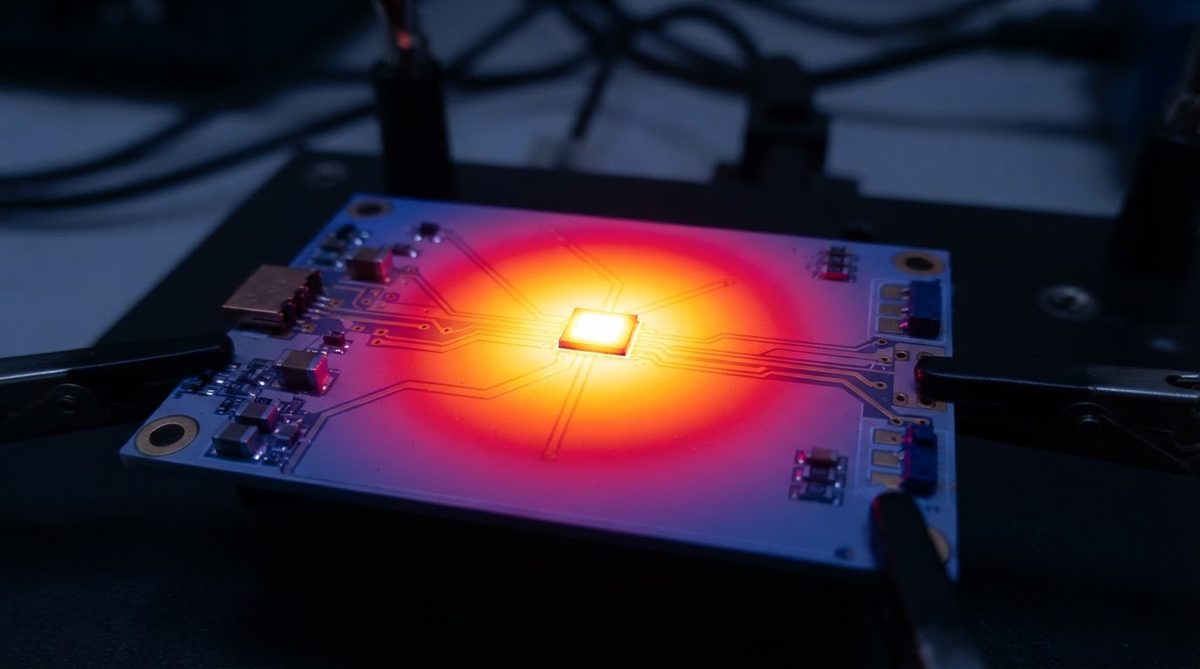
96% alumina is a polycrystalline ceramic body containing approximately 96 wt% aluminum oxide (α-Al2O3) with the balance being a glassy silicate phase formed from sintering aids such as SiO2, MgO, and CaO. This glass phase lowers the sintering temperature to roughly 1 550–1 620 °C compared to >1 700 °C for 99.6% grades, which reduces manufacturing cost. The trade-off is slightly lower thermal conductivity and mechanical strength versus higher-purity grades.
If your thermal budget demands more than 96% alumina can deliver, 99.6% alumina properties show where the higher-purity grade pulls ahead. For applications needing 170 W/m·K or above, see aluminum nitride (AlN) material properties.
Complete Alumina 96% Al2O3 Properties Table
| Property | Value | Unit | Condition / Standard | Source |
|---|---|---|---|---|
| Purity | 96 | wt% Al2O3 | — | CoorsTek ADS-96R |
| Density | 3.72–3.78 | g/cm³ | ASTM C373 | CoorsTek ADS-96R |
| Color | White to ivory | — | Visual | Kyocera A-476 |
| Water absorption | 0.0 | % | ASTM C373 | CoorsTek ADS-96R |
| Grain size (avg.) | 5–10 | µm | SEM cross-section | Kyocera A-476 |
| Thermal conductivity | 24–28 | W/m·K | 25 °C, ASTM E1461 | CoorsTek ADS-96R, Kyocera A-476 |
| Thermal conductivity | 10–14 | W/m·K | 400 °C | Kyocera A-476 |
| CTE | 7.0–7.4 | ppm/°C | 25–300 °C, ASTM E228 | CoorsTek ADS-96R |
| CTE | 7.8–8.2 | ppm/°C | 25–800 °C | CoorsTek ADS-96R |
| Specific heat | 780–800 | J/kg·K | 25 °C | CeramTec Rubalit 708S |
| Flexural strength | 330–380 | MPa | 25 °C, 3-pt bend, ASTM C1161 | CoorsTek ADS-96R |
| Elastic modulus (Young’s) | 310–330 | GPa | ASTM C1259 | CoorsTek ADS-96R |
| Poisson’s ratio | 0.21–0.22 | — | ASTM C1259 | CoorsTek ADS-96R |
| Vickers hardness | 12–13 | GPa | 1 kgf, ASTM C1327 | CoorsTek ADS-96R |
| Fracture toughness (K_IC) | 3.5–4.0 | MPa·√m | SEVNB, ASTM C1421 | CeramTec Rubalit 708S |
| Dielectric constant (εr) | 9.0–9.5 | — | 1 MHz, 25 °C, ASTM D150 | Kyocera A-476 |
| Dielectric constant (εr) | 9.3–9.8 | — | 10 GHz, 25 °C | Kyocera A-476 |
| Loss tangent (tan δ) | 0.0002–0.0010 | — | 1 MHz, 25 °C, ASTM D150 | CoorsTek ADS-96R |
| Dielectric strength | 10–15 | kV/mm | AC, 60 Hz, ASTM D149 | CoorsTek ADS-96R |
| Volume resistivity | >10¹⁴ | Ω·cm | 25 °C, ASTM D1829 | CoorsTek ADS-96R |
| Max. use temperature | 1 600+ | °C | Inert atm., no load | CeramTec Rubalit 708S |
| Thermal shock resistance (ΔT) | 200–250 | °C | Water quench, no cracking | CeramTec Rubalit 708S |
Typical values for commercially available material, for comparison only. Confirm against the datasheet for your specific grade.
Thermal Alumina 96% Al2O3 Properties in Detail
At room temperature, 96% alumina delivers 24–28 W/m·K. That figure drops to roughly 10–14 W/m·K at 400 °C because phonon scattering increases with temperature. If your device junction sits at 150 °C during steady-state operation, plan on an effective substrate thermal conductivity closer to 18–22 W/m·K, not the room-temperature value.
Enter your substrate dimensions, thickness, and dissipated power below to estimate junction-to-baseplate thermal resistance using alumina 96% Al2O3 properties at your actual operating temperature.
Worked Example: Thermal Resistance of a 96% Al2O3 Substrate
Assume a 25.4 × 25.4 mm substrate, 0.635 mm thick, with uniform heat flux. At 25 °C:
R_th = t / (k × A) = 0.000635 m / (26 W/m·K × 0.000645 m²) = 0.038 °C/W
For the same geometry in AlN at 180 W/m·K, R_th drops to 0.0055 °C/W — a 7× improvement. Whether that matters depends on your total thermal stack. If the solder joint and heat-sink interface already contribute 1.5 °C/W, the 0.032 °C/W difference in substrate resistance is negligible. Run the full stack before upgrading to AlN.
For available 96% alumina thickness and tolerance options, thinner substrates (0.25 mm) cut thermal resistance almost in half but reduce mechanical rigidity.
Electrical Properties: Dielectric and Insulation
The dielectric constant of 96% alumina is 9.0–9.5 at 1 MHz, rising slightly to 9.3–9.8 at 10 GHz. This is significantly higher than FR-4 (4.2–4.5) or Rogers RO4003C (3.38). For RF stripline or microstrip designs, the higher εr means narrower traces for a given impedance, which can be an advantage for miniaturisation but increases conductor loss per unit length.
Loss tangent at 1 MHz is very low — 0.0002 to 0.0010 — making 96% alumina suitable for many RF filter and resonator applications up to a few GHz. Above 10 GHz, the glassy phase in 96% alumina raises losses noticeably compared to 99.6% alumina or AlN. For high-frequency designs, review the alumina 96% Al2O3 properties table above alongside AlN dielectric data, or consider 99.6% alumina.
Dielectric strength of 10–15 kV/mm (AC, 60 Hz, per ASTM D149) provides comfortable insulation margin for most power-electronics substrates. A 0.635 mm substrate withstands 6.4–9.5 kV before breakdown.
Mechanical Properties and Handling
Flexural strength of 330–380 MPa sounds high in absolute terms, but alumina is a brittle material with fracture toughness of only 3.5–4.0 MPa·√m. It does not yield before fracture. Point loads during pick-and-place, screw-down mounting, or connector insertion can crack a substrate if the support geometry concentrates stress.
Practical handling rules: support the substrate across its full area during reflow, avoid cantilevered sections longer than 15 mm without mid-span support, and use compliant thermal interface materials rather than rigid clamps against the ceramic.
For applications where mechanical shock or vibration is severe — automotive inverters, downhole tools — silicon nitride (Si3N4) substrate properties show fracture toughness of 6–7 MPa·√m and flexural strength above 700 MPa, at significantly higher cost.
How 96% Alumina Compares to Other Ceramic Substrates
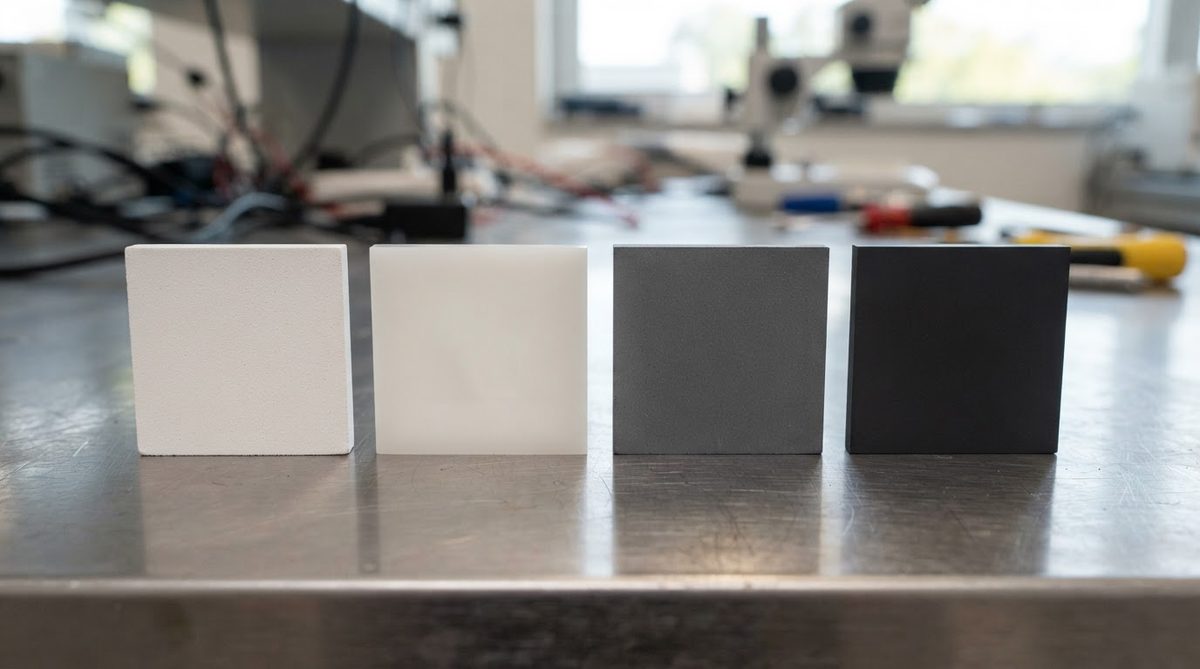
| Parameter | 96% Al2O3 | 99.6% Al2O3 | AlN | Si3N4 |
|---|---|---|---|---|
| Thermal conductivity (W/m·K, 25 °C) | 24–28 | 28–35 | 170–200 | 70–90 |
| CTE (ppm/°C, 25–300 °C) | 7.0–7.4 | 7.0–7.2 | 4.5–5.0 | 2.5–3.2 |
| Dielectric constant (1 MHz) | 9.0–9.5 | 9.7–10.0 | 8.5–9.0 | 8.0–8.5 |
| Flexural strength (MPa) | 330–380 | 350–400 | 300–350 | 700–900 |
| Fracture toughness (MPa·√m) | 3.5–4.0 | 3.5–4.5 | 2.5–3.0 | 6.0–7.0 |
| Relative cost (per unit area) | 1× | 1.3–1.8× | 3–5× | 4–6× |
Typical values for commercially available material, for comparison only. Confirm against the datasheet for your specific grade.
Sources: CoorsTek ADS-96R and ADS-996 datasheets; Kyocera A-476 and AN-230 datasheets; CeramTec Rubalit and Alunit datasheets.
Surface Finish and Roughness
As-fired 96% alumina has a typical surface roughness (Ra) of 0.4–0.8 µm. This is adequate for thick-film screen printing but may be too rough for thin-film sputtered metallisation, which generally needs Ra below 0.1 µm. Lapped and polished 96% alumina can reach Ra of 0.02–0.05 µm, though this adds cost. For a deeper look at surface preparation, see 96% alumina surface finish and roughness data.
When NOT to Use 96% Alumina
High thermal flux (>50 W/cm²): If your device dissipates more than roughly 50 W/cm² and the thermal stack is already optimised, the 24–28 W/m·K conductivity of 96% alumina becomes the bottleneck. Switch to AlN or a DBC/AMB on AlN.
Millimetre-wave RF (>20 GHz): The glassy phase in 96% alumina increases dielectric loss at millimetre-wave frequencies. Use 99.6% alumina or AlN for frequencies above 20 GHz.
Severe mechanical shock: Fracture toughness of 3.5–4.0 MPa·√m is marginal for drop or vibration environments. Si3N4 is the better ceramic; an MCPCB or IMS board may also suffice if thermal demands are moderate.
Cost-sensitive, low-power consumer boards: If your device runs below 1 W total and operates at ambient temperatures, FR-4 or an aluminum MCPCB costs a fraction of any ceramic substrate. The alumina 96% Al2O3 properties advantage in thermal performance simply is not needed here.
Frequently Asked Questions
Is 96% alumina food-safe or biocompatible?
Unmetallised 96% alumina is chemically inert and has been used in dental and orthopaedic implants, though biocompatibility certification depends on the specific grade and sintering-aid composition. Always verify against ISO 10993 testing for your intended use.
Can 96% alumina be laser-cut or machined after firing?
Yes, but only with diamond tooling or CO2/UV laser scribing. Fired alumina cannot be drilled with standard carbide bits. Laser scribing is the most common method for singulation; green-state machining before sintering is cheaper for complex shapes.
Does 96% alumina absorb moisture?
No. Fully sintered 96% alumina has zero water absorption per ASTM C373. It does not require conformal coating for moisture protection, unlike many organic substrates.
What metallisation processes work on 96% alumina?
Thick-film (screen-printed Ag, Au, or AgPd pastes fired at 850 °C), thin-film (sputtered Ti/Ni/Au or Cr/Ni/Au), DBC (direct bond copper), and active metal brazing (AMB) all bond well to 96% alumina. Thick film is the most common and lowest-cost method. The full set of alumina 96% Al2O3 properties — low surface roughness, high-temperature stability, and chemical inertness — makes it compatible with all standard ceramic metallisation routes.
How does thermal conductivity change with temperature?
It decreases. At 25 °C, expect 24–28 W/m·K. At 400 °C, that drops to 10–14 W/m·K (Kyocera A-476 datasheet). Always use the conductivity value at your expected operating temperature for thermal modelling, not the room-temperature spec.
Next Step
If 96% alumina fits your thermal and electrical requirements, the next step is choosing a substrate thickness and surface finish. Review 96% alumina PCB options and sourcing for available configurations, or request a quote with your Gerber files for pricing and lead-time confirmation.