A high temperature PCB 300C-rated assembly requires every layer—substrate, metallization, solder, and passivation—to survive at that temperature, not just the ceramic itself. The substrate is rarely the weak link. Al₂O₃ (96 %) remains mechanically stable to roughly 1 600 °C, AlN to about 1 000 °C in inert atmosphere, and Si₃N₄ to around 1 000 °C. The real ceiling comes from the conductor system, the die-attach material, and the solder joints, which typically fail between 200 °C and 450 °C depending on alloy and bond method.
Key Takeaways
- Ceramic substrates tolerate far higher temperatures than the metals bonded to them; Al₂O₃ 96 % is usable to ~1 600 °C, while gold thick-film conductors are rated to roughly 850 °C in air.
- Standard SAC305 solder (Sn-3.0Ag-0.5Cu) melts at 217–220 °C, making it unsuitable for any high temperature PCB 300C application.
- High-temperature solders such as Au-20Sn (Tm 280 °C) and Au-12Ge (Tm 356 °C) extend the assembly ceiling to roughly 250 °C and 320 °C respectively.
- Above 400 °C, solder is replaced entirely by sintered silver, Au-Au thermocompression, or glass-frit bonding.
- CTE mismatch stress increases with temperature swing; a 300 °C operating range demands careful material pairing or compliant interlayers.
Why the Substrate Is Not the Bottleneck in a High Temperature PCB 300C Design
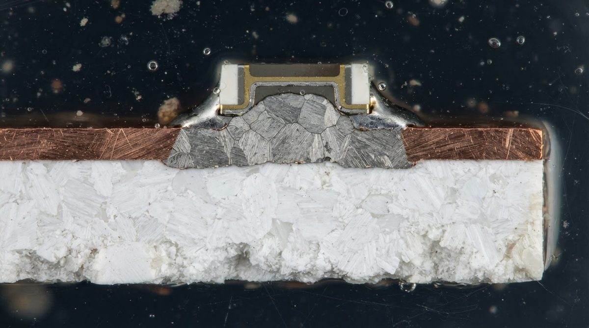
Engineers searching for a high temperature PCB 300C solution often start by comparing substrate materials. That comparison matters, but the ceramic itself almost never sets the operating ceiling. A 96 % alumina substrate retains >90 % of its room-temperature flexural strength (330–380 MPa per ASTM C1161) at 500 °C. Aluminum nitride keeps its 170–200 W/mK thermal conductivity nearly flat to 400 °C before it begins to oxidize in open air above ~700 °C. Silicon nitride offers the best Si₃N₄ thermal performance combined with fracture toughness (6–7 MPa·√m), which resists thermal-shock cracking during rapid heat-up cycles.
The real failure sequence in a high-temperature stack is almost always: solder joint → conductor adhesion → passivation breakdown → substrate. Design effort should follow the same order.
Temperature Limits Layer by Layer
| Layer / Material | Max Continuous Temp | Failure Mode | Source / Basis |
|---|---|---|---|
| FR-4 (Tg 130–170 °C) | 130–170 °C | Glass transition, delamination | IPC-4101, various laminate datasheets |
| Polyimide flex | 250–300 °C | Oxidative degradation | DuPont Kapton HN datasheet |
| Al₂O₃ 96 % | ~1 600 °C | Grain-boundary softening | CoorsTek ADS-96R datasheet |
| AlN | ~1 000 °C (inert), ~700 °C (air) | Surface oxidation in air | Kyocera SH-30 datasheet |
| Si₃N₄ | ~1 000 °C | Slow oxidation | CeramTec SN series datasheet |
| Ag thick-film conductor | ~300 °C (air) | Ag migration, oxidation of glass binder | DuPont / Heraeus paste datasheets |
| Au thick-film conductor | ~850 °C (air) | Diffusion into substrate at extreme temps | Heraeus C8729 datasheet |
| Cu (DBC / AMB) | ~400 °C (inert), ~300 °C (air) | Oxidation, bond-layer degradation | Rogers curamik DBC data |
| SAC305 solder | ~170 °C continuous | Creep, recrystallization | IPC J-STD-006C |
| Au-20Sn solder | ~250 °C | Intermetallic coarsening | Indium Corp. application note |
| Au-12Ge solder | ~320 °C | Voiding at interface | Williams Advanced Materials data |
| Sintered Ag | ~500 °C+ | Ag migration if unpassivated | Heraeus ASP series data |
| Glass-frit seal | ~450 °C | Softening above Tg of frit | Ferro EG series datasheet |
Typical values for commercially available materials, for comparison only. Confirm against the datasheet for your specific grade.
Choosing a Conductor System for a High Temperature PCB 300C and Above
Below 200 °C, standard copper DBC on alumina with SAC solder works fine and costs the least. Between 200 °C and 300 °C, the options narrow. Silver thick-film conductors on Al₂O₃ survive, but silver migration becomes a reliability risk above 250 °C in humid or biased conditions. Gold thick-film paste eliminates migration and pushes the conductor ceiling to roughly 850 °C, but gold conductor paste costs 8–15× more than silver paste per fired layer.
For boards operating continuously above 300 °C—downhole oil-and-gas sensors, jet-engine health monitors, Venus-surface probes—gold thick-film on Al₂O₃ 96 % or 99.6 % is the standard approach. The die-attach shifts to Au-Ge solder or sintered silver, and wire bonds use gold or platinum wire. The entire assembly must avoid tin-bearing alloys, because tin pest and intermetallic growth accelerate rapidly above 200 °C. For a deeper comparison of substrate options, see ceramic substrate materials and their properties.
Enter your substrate dimensions, operating temperature, and power dissipation below to see how junction temperature changes with material choice and thickness.
Worked Example: Selecting Materials for a 350 °C Sensor Board
Suppose you need a pressure-sensor PCB for a geothermal well, operating continuously at 350 °C ambient, with a 5-year service life and no field access for replacement. This is a textbook high temperature PCB 300C-class application where every material decision matters.
- Substrate: Al₂O₃ 96 % — well within its 1 600 °C limit, widely available, and the lowest-cost ceramic option. No need for AlN here because thermal conductivity at 350 °C is adequate for the ~0.5 W dissipation of a MEMS pressure die.
- Conductor: Au thick-film (fired at ~850 °C). Eliminates migration and oxidation concerns at 350 °C.
- Die attach: Au-12Ge preform (Tm 356 °C). Provides a 6 °C margin. Alternatively, sintered Ag at 20 MPa gives a joint stable to >500 °C and higher thermal conductivity (~250 W/mK through the bond line).
- Wire bond: 25 µm Au ball bond. Al wedge bonds form intermetallics with Au pads above 200 °C (Kirkendall voiding), so Au-Au bonding is mandatory.
- Passivation: Overglaze thick-film glass, rated to ~500 °C. Standard solder mask (epoxy-based) chars above 250 °C.
Estimated per-board cost for a 25 × 25 mm single-layer board at 100-piece volume: $35–$55, versus $3–$5 for an equivalent FR-4 board. The premium is justified only when no organic substrate can survive the environment. To estimate thermal path performance for your own geometry, calculate the Rth of your ceramic stack.
CTE Mismatch Gets Worse at High Temperature
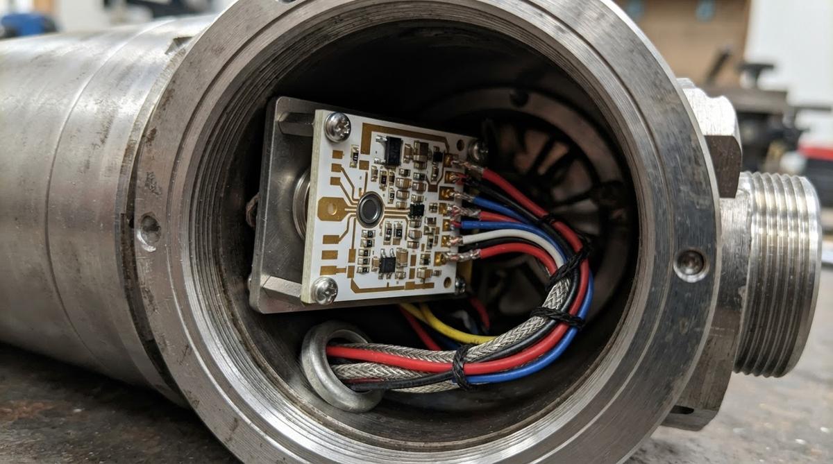
Thermal expansion is roughly linear with temperature for ceramics, but solder creep and conductor stress accumulate over wider ΔT swings. A board cycling between 25 °C and 350 °C sees a ΔT of 325 K. For a silicon die (CTE ~2.6 ppm/K) on Al₂O₃ 96 % (CTE ~7.1 ppm/K at 20–300 °C per CoorsTek), the differential strain over a 10 mm die is:
ΔL = (7.1 − 2.6) × 10⁻⁶ × 10 mm × 325 = 14.6 µm
That 14.6 µm shear displacement at the die-attach interface causes fatigue cracking in rigid solders after hundreds of cycles. Sintered silver, with its porous microstructure, absorbs this strain better than bulk Au-Sn. For die larger than ~8 mm, consider AlN (CTE ~4.5 ppm/K) to halve the mismatch. More detail on thermally conductive ceramic PCB options covers AlN and Si₃N₄ side by side.
When NOT to Use a Ceramic High Temperature PCB 300C Board
If your maximum operating temperature stays below 150 °C, standard FR-4 or high-Tg FR-4 (Tg 170 °C) is cheaper by 10–20× and easier to source. Between 150 °C and 250 °C, polyimide flex or high-Tg polyimide rigid boards may suffice and still accept standard SMT assembly. Ceramic becomes the clear choice only above ~250 °C continuous, or when you need the combination of high temperature and high thermal conductivity, high-frequency dielectric stability, or hermeticity.
Also avoid ceramic if your board exceeds roughly 150 × 150 mm. Large ceramic panels are fragile, expensive, and prone to warpage under uneven thermal loads. For large-format high-temperature needs, metal-core PCBs with polyimide dielectrics or bolt-mounted ceramic daughter cards on a metal carrier are more practical.
Reliability and Testing at Extreme Temperature
Standard IPC qualification tests (IPC-6012 class 3) do not cover operation above 150 °C. For a high temperature PCB 300C-rated design, you need application-specific qualification. Common tests include:
- Thermal cycling: MIL-STD-883 Method 1010, Condition C (−65 °C to +300 °C or custom range), 500–1 000 cycles minimum.
- High-temperature storage: 1 000 hours at max operating temperature, measuring conductor resistance shift and adhesion pull strength before and after.
- Thermal shock: JEDEC JESD22-A104, modified for higher peak temperature. Ceramic substrates generally pass; the solder joints and wire bonds are the items under test.
Gold thick-film on Al₂O₃ 96 % routinely passes 1 000 cycles at −55 °C to +300 °C with <5 % resistance shift, per published data from Heraeus and DuPont (now KYOCERA AVX). Silver thick-film shows 10–20 % resistance drift under the same profile due to glass-binder softening. For the full ceramic PCB manufacturing sequence, including firing profiles for thick-film pastes, see our process overview.
Frequently Asked Questions
Can I use standard SAC solder on a high temperature PCB 300C board?
No. SAC305 melts at 217–220 °C and is generally derated to ~170 °C continuous. At 300 °C the joint is liquid. Use Au-20Sn (up to ~250 °C), Au-12Ge (up to ~320 °C), or sintered silver for anything above 250 °C.
Does aluminum nitride oxidize at high temperature?
Yes. AlN forms a surface oxide layer (Al₂O₃) in air above roughly 700 °C. Below 700 °C in air, or at higher temperatures in nitrogen or vacuum, oxidation is negligible. For most electronics applications at 300–500 °C, AlN is safe in air.
What is the cheapest ceramic substrate for a 300 °C board?
Al₂O₃ 96 % is the lowest-cost option at roughly $0.03–$0.08/cm² in volume for bare substrate. It handles 300 °C with wide margin. AlN costs 3–5× more and is only justified when you need its higher thermal conductivity (170–200 W/mK versus 24–28 W/mK).
Do I need gold conductors, or will silver work at 300 °C?
Silver thick-film conductors can physically survive 300 °C, but silver migration under DC bias and resistance drift from glass-binder degradation make them unreliable for long-term service above ~250 °C. Gold thick-film is the standard choice for 300 °C+ applications.
Can multilayer ceramic boards operate at 300 °C?
Yes. HTCC (high-temperature co-fired ceramic) multilayer ceramic PCBs use tungsten or molybdenum internal conductors co-fired with the alumina at ~1 600 °C. The finished multilayer is a monolithic ceramic body with no organic layers, so it withstands 300 °C indefinitely.
How do I protect exposed conductors from oxidation at high temperature?
Apply a thick-film overglaze (glass passivation) fired at 500–600 °C. This seals the conductor surface against oxidation and contamination. For pads that must remain solderable, use gold metallization, which resists oxidation to ~850 °C in air and needs no additional protection.
Next Step
If your application runs above 250 °C, define the exact temperature profile—peak, continuous, and number of thermal cycles—before selecting materials. Share that profile along with your Gerber files or a sketch, and our engineers can recommend the substrate, metallization, and die-attach combination that fits your budget and reliability target. Browse common ceramic PCB questions or request a quote directly.