The bulk ceramic in a ceramic PCB can withstand 800 °C to over 1 700 °C continuously, depending on the substrate material. In practice, the maximum operating temperature of the assembled board is almost always set by the metallization or solder, not the ceramic itself. A 96 % alumina substrate survives above 1 600 °C, but a standard SAC305 solder joint fails around 217 °C. Knowing both limits is the difference between a reliable design and a field failure.
Bare Substrate Temperature Limits by Material
The table below lists the continuous-use ceiling for common ceramic PCB substrates. These are material limits only, before any metal or solder is applied.
| Substrate | Max continuous temp | Melting / decomposition point | Condition | Source |
|---|---|---|---|---|
| Al₂O₃ 96 % | ~1 600 °C | ~2 050 °C | Inert atmosphere | CoorsTek ADS-96R datasheet |
| Al₂O₃ 99.6 % | ~1 700 °C | ~2 050 °C | Inert atmosphere | Kyocera A-493 datasheet |
| AlN | ~1 000 °C (air); ~1 700 °C (N₂) | Decomposes ~2 200 °C | Oxidises above ~700 °C in air | Maruwa HA-series datasheet |
| Si₃N₄ | ~1 200 °C (air) | Decomposes ~1 900 °C | Oxidation-resistant | CeramTec SN-series datasheet |
Typical values for commercially available material, for comparison only. Confirm against the datasheet for your specific grade.
AlN deserves a specific note. In air above roughly 700 °C, aluminum nitride oxidises to alumina, degrading thermal conductivity over time. If your application exceeds 700 °C in an oxygen-containing environment, AlN is not a good choice unless the surface is passivated or the atmosphere is controlled. For more on how Si₃N₄ compares thermally, that material offers better oxidation resistance at elevated temperatures.
What Actually Limits the Assembled Board
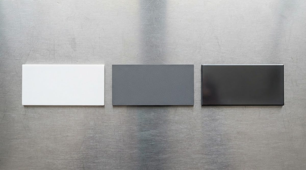
No one runs a bare ceramic slab in a product. The real temperature ceiling is determined by the weakest link in the stack: substrate, metallization, solder, and any attached components.
| Layer / joint | Typical max temp | Notes |
|---|---|---|
| SAC305 solder | ~150–170 °C (long-term reliable) | Liquidus 217–220 °C; creep accelerates above 150 °C |
| High-temp solder (Au-Sn, Au-Ge) | ~280–360 °C | Au80Sn20 liquidus 280 °C |
| Ag sintered die attach | ~400–600 °C | No remelting; limited by oxidation of Ag in air |
| Thick-film Ag/Pd metallization | ~300–400 °C (air) | Ag migration above 300 °C in humid conditions |
| Thick-film Au metallization | ~500 °C+ | Inert; limited by glass binder phase |
| DBC Cu on Al₂O₃ | ~400–500 °C | Cu-O eutectic bond formed at 1 065 °C; stable below ~500 °C |
| AMB Cu on Si₃N₄ / AlN | ~400–500 °C | Active braze (Ag-Cu-Ti); limited by braze layer |
Typical values for commercially available material, for comparison only. Confirm against the datasheet for your specific grade.
The practical takeaway: a standard ceramic PCB assembly with SAC305 solder is reliable to roughly 150–170 °C continuous. Switching to Au-Sn solder and thick-film Au metallization pushes the ceiling to around 300 °C. Beyond that, you move to sintered die attach and wire bonding, eliminating solder entirely. Boards designed for 200–500 °C environments require careful high-temperature PCB design choices at every layer.
Worked Example: Derating for a 250 °C Application
Suppose you need a sensor interface board that operates continuously at 250 °C ambient in a downhole oil-and-gas tool.
- Substrate: 96 % Al₂O₃ — ceiling ~1 600 °C. No issue.
- Metallization: Thick-film Au — stable above 500 °C. No issue.
- Solder: SAC305 liquidus is 217 °C. At 250 °C it is molten. Fail. Switch to Au80Sn20 (liquidus 280 °C). At 250 °C you have only 30 °C margin. Acceptable for steady-state if no power cycling, but risky under thermal shock.
- Alternative: Use Ag sintered die attach for power components and Au-Sn for passives. This gives 30–350 °C of margin depending on the joint.
- Components: Verify every IC is rated to 250 °C. Most commercial silicon tops out at 125–150 °C. You may need SiC or SOI parts.
The ceramic is never the bottleneck here. The solder and the silicon are. Running a thermal resistance calculation at this stage confirms whether junction temperatures stay within die ratings even at 250 °C ambient.
Thermal Cycling and Long-Term Degradation
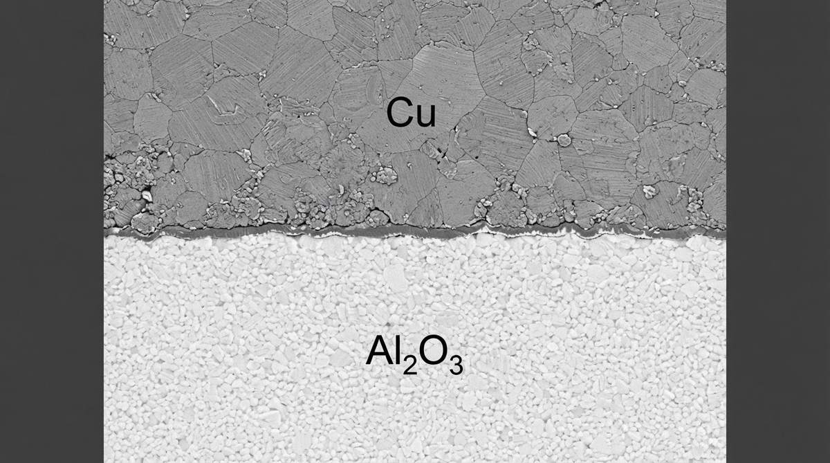
A substrate that survives 1 000 °C in a furnace may still fail at 300 °C in the field if the board cycles between room temperature and operating temperature thousands of times. CTE mismatch between the ceramic (6–8 ppm/°C for alumina) and copper metallization (17 ppm/°C) generates stress at every cycle. DBC bonds on alumina typically survive 2 000–5 000 cycles from −40 °C to +250 °C (per JEDEC JESD22-A104 style testing). AMB bonds on Si₃N₄ can exceed 10 000 cycles under the same profile because Si₃N₄ is tougher and the active braze absorbs more strain.
If your application involves aggressive thermal cycling above 200 °C, Si₃N₄ AMB substrates are the safer choice despite higher cost. For steady-state high temperature with mild cycling, Al₂O₃ DBC or thick-film is usually sufficient.
When NOT to Use a Ceramic PCB for High Temperature
Ceramic is not always the answer, even when the temperature is high.
- Below 150 °C continuous: Standard FR-4 (Tg 170 °C) or polyimide (rated to ~260 °C short-term) may be adequate and far cheaper. Ceramic adds cost with no thermal benefit at these temperatures.
- Large board area, low power density: Metal-core PCBs (MCPCBs) handle 150 °C and cost a fraction of ceramic per square centimeter. If your heat is spread, not concentrated, MCPCB wins on cost.
- Extreme mechanical shock or vibration: Ceramic is brittle. A polyimide flex or rigid-flex board survives drops and vibration that would crack a ceramic substrate. If the environment is both hot and mechanically violent, consider a high thermal conductivity PCB on an insulated metal substrate with conformal coating instead.
- Above 500 °C with complex routing: At these temperatures, even thick-film metallization degrades. You are likely looking at bare ceramic sensor elements with wire bonds, not a traditional PCB. The “PCB” concept stops being useful.
Frequently Asked Questions
Does ceramic PCB max temperature change with thickness?
No. The bulk material limit is the same whether the substrate is 0.25 mm or 2.0 mm thick. Thicker substrates do reduce thermal shock resistance because the temperature gradient across the cross-section is steeper, which increases cracking risk during rapid heating or cooling.
Can I reflow solder on a ceramic board at 260 °C?
Yes. Standard SAC305 reflow profiles peak at 245–260 °C for 30–90 seconds, which is well within the ceramic’s capability. The substrate does not care about reflow temperatures. Ensure your metallization adhesion and pad finish are specified for the reflow profile you plan to use.
Is AlN better than alumina for high-temperature use?
Not necessarily. AlN oxidises in air above roughly 700 °C, which degrades its thermal conductivity over time. Alumina is already an oxide and does not degrade further. AlN is chosen for its thermal conductivity (170–200 W/mK), not for its temperature ceiling. For extreme heat in air, 99.6 % alumina or Si₃N₄ is more stable.
What adhesive can I use to mount a ceramic PCB at 300 °C?
Standard epoxy adhesives fail above 200–250 °C. For 300 °C continuous mounting, use ceramic-filled silicone adhesives (rated to ~300 °C), or mechanical clamping with a compliant thermal interface material such as graphite sheet. Above 400 °C, brazing or bolting is typically the only reliable attachment method.
Do surface finishes affect the max operating temperature?
Yes. ENIG finishes are reliable to about 150–200 °C. Bare thick-film gold is stable above 500 °C. Immersion silver and OSP oxidise and degrade well below 300 °C. Choose the finish to match the operating temperature, not just the soldering process.