In the ceramic vs metal core PCB debate, ceramic wins on thermal conductivity, dielectric strength, and maximum operating temperature, but costs 3–10× more per unit area and is limited in panel size. MCPCBs win on cost and availability for moderate-power applications such as LED lighting. The right choice depends on your power density, isolation voltage, and budget.
Key Takeaways
- 96% alumina ceramic substrates conduct heat at 24–28 W/mK; aluminum nitride (AlN) reaches 170–200 W/mK. A typical aluminium-base MCPCB delivers only 1–4 W/mK through its dielectric layer.
- Ceramic substrates operate continuously above 800 °C. MCPCB dielectric layers degrade above 130–150 °C.
- Ceramic provides volumetric dielectric strength of 10–15 kV/mm (96% Al₂O₃, per CoorsTek datasheet). MCPCB dielectric layers typically rate 3–6 kV at 75–150 µm thickness.
- MCPCBs cost roughly $0.02–$0.08/cm² in volume; ceramic boards start around $0.20–$0.80/cm² for 96% alumina, rising further for AlN.
- For LED arrays under 10 W/cm², MCPCB is usually the pragmatic choice. Above that, or where isolation voltage exceeds 2 kV, ceramic pulls ahead.
What Is a Metal Core PCB?
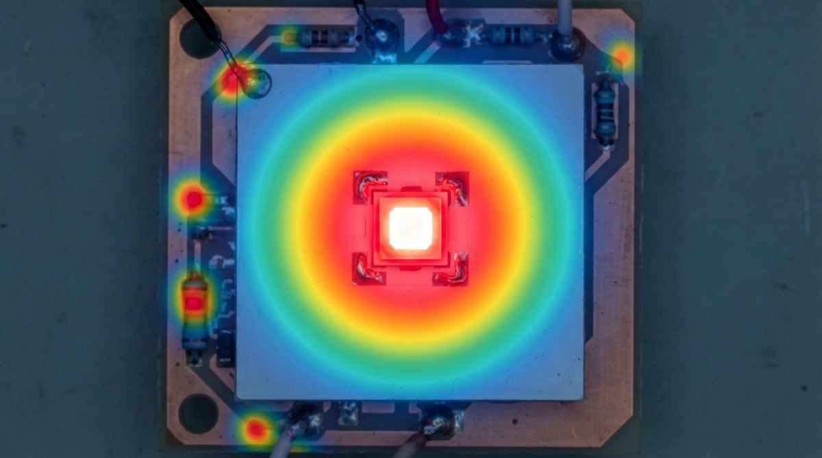
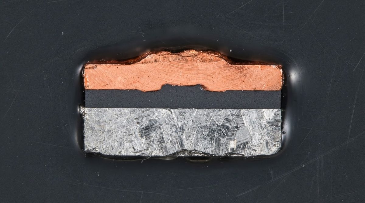
A metal-core PCB is a standard copper-circuit board built on a metal base plate—usually aluminium 5052 or 6061, sometimes copper—with a thin thermally conductive but electrically insulating dielectric layer (50–150 µm) bonding the circuit copper to the metal core. The dielectric is typically an epoxy or polyimide filled with ceramic particles (Al₂O₃, BN, or AlN powder). Heat flows from the copper traces, through the dielectric, into the metal base, and out to a heatsink.
The bottleneck is that dielectric layer. Even premium MCPCB dielectrics reach only 3–5 W/mK. The aluminium base itself conducts at ~150 W/mK, but the thin insulator between circuit and base dominates total thermal resistance. This is why MCPCB datasheets quote “thermal conductivity” numbers that look impressive until you notice they refer to the metal base, not the dielectric.
A ceramic PCB, by contrast, uses the ceramic body itself as both the dielectric and the structural substrate. There is no polymer dielectric bottleneck. The full substrate thickness conducts heat at the ceramic’s native thermal conductivity. Understanding this distinction is the foundation of any ceramic vs metal core PCB evaluation.
Ceramic vs Metal Core PCB: Thermal Performance
The single most common reason engineers consider ceramic over MCPCB is thermal resistance. Below is a worked example showing why the numbers matter more than the marketing.
Worked Example: 20 W LED Die on a 10 × 10 mm Footprint
Assume one-dimensional steady-state conduction through the substrate directly beneath the die. Thermal resistance Rth = t / (k × A), where t = thickness, k = thermal conductivity, A = area.
| Parameter | MCPCB (dielectric layer) | 96% Al₂O₃ Ceramic | AlN Ceramic |
|---|---|---|---|
| Thickness (t) | 75 µm (0.075 mm) | 635 µm (0.635 mm) | 635 µm (0.635 mm) |
| Thermal conductivity (k) | 2.2 W/mK | 25 W/mK | 180 W/mK |
| Area (A) | 1 cm² (1 × 10⁻⁴ m²) | 1 cm² | 1 cm² |
| Rth through substrate | 0.34 °C/W | 0.25 °C/W | 0.035 °C/W |
| ΔT at 20 W | 6.8 °C | 5.1 °C | 0.7 °C |
Typical values for commercially available material, for comparison only. Confirm against the datasheet for your specific grade.
The MCPCB dielectric is much thinner, which partially compensates for its low conductivity. For a 20 W die on a 1 cm² pad, the MCPCB dielectric adds about 6.8 °C. The alumina ceramic, eight times thicker but with 11× higher conductivity, adds only 5.1 °C. AlN is in a different league entirely at 0.7 °C.
The gap widens sharply as power density increases. At 100 W/cm², the MCPCB dielectric alone contributes 34 °C of rise—often unacceptable when junction temperature budgets are tight. The AlN substrate contributes just 3.5 °C.
Enter your own substrate dimensions and dissipated power below to estimate thermal resistance through the dielectric or ceramic layer.
[pcb_calc type=”metal-core-thermal”]
Head-to-Head Specification Comparison
The table below summarises the key parameters that separate ceramic and metal core PCB substrates across thermal, electrical, mechanical, and commercial dimensions.
| Parameter | MCPCB (Al base) | Ceramic – 96% Al₂O₃ | Ceramic – AlN | Unit | Source / Condition |
|---|---|---|---|---|---|
| Substrate thermal conductivity | 1–4 (dielectric layer) | 24–28 | 170–200 | W/mK | Bergquist / CoorsTek datasheets, 20 °C |
| Max continuous operating temp. | 130–150 | 800+ | 800+ | °C | Dielectric Tg vs ceramic stability |
| Dielectric strength | 3–6 kV (at 75–150 µm) | 10–15 kV/mm | 12–17 kV/mm | — | Per ASTM D149 / CoorsTek |
| CTE | 22–24 (Al base) | 6.5–7.2 | 4.3–4.7 | ppm/°C | 20–300 °C range |
| Typical max panel size | 600 × 500 mm | ~190 × 140 mm (Al₂O₃) | ~114 × 114 mm | mm | Standard production limits |
| Cost per cm² (volume) | $0.02–$0.08 | $0.20–$0.80 | $1.00–$4.00 | USD | Approximate, varies with qty |
| Lead time (prototype) | 5–10 days | 10–20 days | 15–25 days | — | Typical industry range |
Typical values for commercially available material, for comparison only. Confirm against the datasheet for your specific grade.
CTE Match to Semiconductors
Silicon has a CTE of about 2.6 ppm/°C. GaN-on-SiC sits around 3.2–4.5 ppm/°C. An aluminium MCPCB base at 22–24 ppm/°C creates a large CTE mismatch that stresses solder joints during thermal cycling. Ceramic substrates are far closer: AlN at 4.3–4.7 ppm/°C is nearly matched to SiC and GaN devices, and 96% alumina at 6.5–7.2 ppm/°C is still much better than aluminium.
This matters most in power modules and RF amplifiers that see repeated thermal excursions. If your device cycles between −40 °C and +150 °C thousands of times, the solder joint reliability difference between a CTE-matched ceramic and a CTE-mismatched MCPCB can be the difference between a 20-year field life and a 3-year one. For an in-depth look at ceramic substrate materials, see the alumina vs aluminum nitride comparison.
Electrical Isolation and High-Voltage Applications
MCPCB dielectric layers provide isolation, but at thin layers (75–150 µm) the breakdown voltage is modest—typically 3–6 kV. Partial discharge inception voltage (PDIV) is often lower still. For applications requiring creepage and clearance per IEC 60664 at system voltages above 1 kV, the MCPCB dielectric may not provide sufficient margin.
Ceramic substrates offer volumetric dielectric strength of 10–15 kV/mm for alumina and 12–17 kV/mm for AlN (per CoorsTek ADS-996 and Maruwa AlN datasheets). A 0.635 mm alumina substrate can withstand over 6 kV; a 1.0 mm substrate exceeds 10 kV. This is why DBC and AMB ceramic processes dominate in high-voltage SiC power modules rated at 1.2–3.3 kV. In any ceramic vs metal core PCB selection for power electronics, isolation voltage is often the deciding factor.
Where MCPCB Wins
MCPCBs are the right call for a large set of real-world projects:
- LED lighting arrays. Most commercial LED boards dissipate under 5 W/cm². The MCPCB dielectric handles this easily, and the aluminium base doubles as the heatsink. Cost per board can be 5–10× lower than ceramic. For a focused comparison in this application, see the star board ceramic vs MCPCB analysis.
- Large-area boards. If your design needs a 300 × 200 mm substrate, ceramic is not available in that size. MCPCB panels run up to 600 × 500 mm.
- Cost-sensitive consumer products. An MCPCB at $0.03/cm² in 10k quantity is a different conversation from a ceramic board at $0.40/cm².
- Fast prototyping. MCPCB vendors deliver in 5–7 days. Ceramic prototypes typically take 10–20 days.
When NOT to Use Ceramic (Choose MCPCB or FR-4 Instead)
Ceramic is overkill—and an unnecessary cost—when any of these apply:
- Power density is below 5 W/cm² and operating temperature stays under 120 °C. Standard MCPCB or even FR-4 with thermal vias will suffice.
- Board area exceeds roughly 150 × 150 mm. Ceramic substrates are not available in large formats.
- The application involves mechanical shock or vibration with risk of point impact. Ceramic substrates are brittle (fracture toughness of 96% Al₂O₃ is ~3.5 MPa·√m, per ASTM C1161). An MCPCB or flex circuit absorbs impact better.
- Budget is the primary constraint and the thermal or voltage requirements do not force a ceramic solution.
Decision Checklist: Ceramic vs Metal Core PCB
Run through these five questions for your specific board. If you answer “yes” to two or more, ceramic is likely the better substrate.
- Is your power density above 10 W/cm² at the hottest component?
- Does the board need to survive continuous temperatures above 150 °C?
- Is isolation voltage above 2 kV required?
- Does CTE mismatch to your die or package cause reliability concern over the product’s lifetime thermal cycles?
- Is board area under 100 × 100 mm, making ceramic panel size a non-issue?
If all five answers are “no,” an MCPCB or FR-4 is almost certainly the more practical choice.
FAQ
Can I reflow solder components onto a ceramic PCB the same way as an MCPCB?
Yes. Ceramic PCBs with DPC, DBC, or thick-film metallisation are compatible with standard lead-free reflow profiles (peak 245–260 °C). The ceramic substrate easily tolerates these temperatures. Preheat ramp rates should stay under 3 °C/s to avoid thermal shock on thicker substrates. More detail is available in the guide on soldering to ceramic PCBs.
Does an MCPCB need a separate heatsink?
Usually yes. The aluminium base improves heat spreading but is rarely thick enough to act as a standalone heatsink. Most MCPCB designs bolt the board to an external aluminium or copper heatsink with thermal interface material (TIM) between them.
What is the typical lifespan difference under thermal cycling?
In accelerated thermal cycling tests (−40 °C to +150 °C, per IPC-9701), ceramic DBC substrates commonly survive 2,000–5,000+ cycles before solder-joint failure. MCPCB assemblies with high-CTE mismatch to the die often show cracks at 500–1,500 cycles under the same profile. Actual field life depends heavily on cycle amplitude and solder alloy.
Is there a hybrid option—ceramic on a metal base?
Yes. Active metal brazed (AMB) ceramic substrates are often soldered or sintered onto copper or AlSiC baseplates. This gives you the ceramic’s dielectric and CTE properties with a metal base for mechanical mounting and heat spreading. This approach is standard in IGBT and SiC power modules.
Are there weight differences I should factor in?
Alumina (96% Al₂O₃) has a density of about 3.7–3.8 g/cm³. Aluminium is 2.7 g/cm³. For small boards under 50 × 50 mm the difference is negligible. For larger assemblies or aerospace applications, the weight delta can matter and should be calculated per your specific substrate thickness.
Next Step
If your ceramic vs metal core PCB analysis points toward ceramic, the next step is to compare specific ceramic substrate grades. The ceramic PCB comparison hub covers alumina, AlN, and Si₃N₄ side by side. When you are ready to get pricing on your board, request a quote with your Gerber files or drawing and we will confirm the best substrate and process for your design.