When engineers evaluate aluminum nitride AlN vs FR4, the headline difference is thermal conductivity: AlN conducts heat roughly 500–700× better than FR-4—170–230 W/mK versus 0.25–0.35 W/mK—while maintaining dielectric strength above 15 kV/mm. FR-4 is cheaper, easier to machine, and available from every board shop on earth. The decision between aluminum nitride AlN vs FR4 comes down to whether your thermal or high-frequency requirements physically cannot be met by an organic laminate.
Key Takeaways
- AlN thermal conductivity (170–230 W/mK at 25 °C, per Kyocera SH-30 datasheet) is roughly three orders of magnitude higher than FR-4 (0.25–0.35 W/mK, per IPC-4101 Spec Sheet 99).
- FR-4 glass transition temperature (Tg) is typically 130–180 °C; AlN remains mechanically and electrically stable above 1 000 °C in inert atmospheres.
- AlN substrates cost approximately 30–80× more per cm² than FR-4 in production volumes, depending on metallisation process and quantity.
- FR-4 dielectric constant is 4.2–4.7 at 1 GHz; AlN is 8.5–9.0 at 1 GHz (Maruwa HA-series datasheet), which affects impedance matching at RF frequencies.
- AlN’s CTE of 4.3–4.7 ppm/°C closely matches silicon (2.6 ppm/°C) and SiC (4.0 ppm/°C), reducing solder-joint fatigue in power modules.
Aluminum Nitride AlN vs FR4: Property-by-Property Comparison
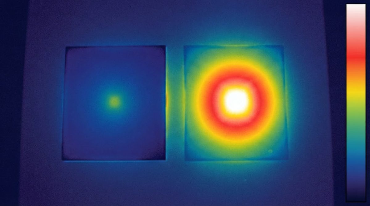
The table below puts the two materials side by side on every parameter that typically drives substrate selection. All values are at 25 °C unless stated otherwise.
| Parameter | AlN | FR-4 | Unit | Condition | Source |
|---|---|---|---|---|---|
| Thermal conductivity | 170–230 | 0.25–0.35 | W/mK | 25 °C | Kyocera SH-30 / IPC-4101 |
| Dielectric strength | 15–17 | 20–25 | kV/mm | 25 °C, AC | Maruwa HA-230 / UL 796 |
| Dielectric constant (εr) | 8.5–9.0 | 4.2–4.7 | — | 1 GHz | Maruwa / IPC-TM-650 2.5.5.9 |
| Loss tangent (tan δ) | 0.0003–0.001 | 0.015–0.025 | — | 1 GHz | Maruwa / Isola 370HR datasheet |
| CTE | 4.3–4.7 | 14–17 (x/y), 50–70 (z) | ppm/°C | 25–300 °C | CoorsTek ADS-996 / IPC-TM-650 |
| Max continuous temp | > 1 000 (inert) / ~700 (air, oxidation onset) | 130–180 (Tg), ~300 decomposition | °C | — | Kyocera / IPC-4101 |
| Flexural strength | 300–400 | 415–550 | MPa | ASTM C1161 / IPC-TM-650 | CoorsTek / Isola |
| Volume resistivity | > 10¹⁴ | ~10⁸–10¹⁰ | Ω·cm | 25 °C | Maruwa / IPC-4101 |
| Typical substrate cost | $15–$60 | $0.20–$0.80 | per 25×25 mm piece | Qty 100, unmetallised | Market pricing, 2024 |
Typical values for commercially available material, for comparison only. Confirm against the datasheet for your specific grade.
Two things jump out from this aluminum nitride AlN vs FR4 comparison. First, AlN’s thermal conductivity advantage is so large that no design trick—thicker copper pours, more vias, thermal coins—can close the gap on FR-4. Second, FR-4’s dielectric strength is actually slightly higher per unit thickness. AlN wins on volume resistivity and loss tangent, which matters for high-voltage isolation and RF signal integrity. For a broader look at whether ceramic PCB is better than FR-4, the answer depends on which of these rows dominates your design.
Thermal Performance: A Worked Example
Consider a 10 W GaN HEMT die mounted on a 25 × 25 mm substrate, 0.635 mm thick, with heat sinking on the opposite face. The one-dimensional thermal resistance through the substrate alone is:
Rth = t / (k × A)
For AlN (k = 180 W/mK):
Rth = 0.000635 / (180 × 0.000625) = 0.0056 °C/W
For FR-4 (k = 0.3 W/mK):
Rth = 0.000635 / (0.3 × 0.000625) = 3.39 °C/W
At 10 W dissipation, the FR-4 substrate alone adds 33.9 °C to the junction-to-case temperature rise. The AlN substrate adds 0.056 °C. That 34 °C difference is often the margin between meeting and missing a junction temperature spec. In practice, interface layers, solder, and heat-sink resistance dominate the total stack, but the substrate contribution on FR-4 is large enough to be the bottleneck in any power-dense layout.
Enter your own substrate dimensions, material, and dissipated power below to estimate the thermal resistance and temperature rise for your specific design.
When AlN Outperforms FR-4
Power electronics and wide-bandgap semiconductors
SiC and GaN devices switch at junction temperatures above 175 °C. FR-4’s Tg sits below that. AlN’s CTE match to SiC (4.0 vs 4.5 ppm/°C) also reduces solder-joint thermal fatigue during power cycling. Most SiC half-bridge modules from Infineon and Wolfspeed specify ceramic substrates for exactly this reason. If you are comparing AlN against 96% alumina substrates for a power module, the deciding factor is usually whether the die dissipation density exceeds what alumina’s 24–28 W/mK can handle.
High-frequency and mmWave circuits
AlN’s loss tangent below 0.001 at 1 GHz makes it suitable for RF front-ends where FR-4’s 0.02 tan δ causes unacceptable insertion loss. The higher εr (8.5–9.0) shrinks trace widths for a given impedance, which can be an advantage or a disadvantage depending on your layout density. At 77 GHz automotive radar frequencies, AlN thin-film substrates are common.
High-temperature environments
Downhole oil-and-gas sensors, jet engine monitoring, and geothermal instrumentation regularly exceed 250 °C. FR-4 cannot survive there. AlN with refractory metallisation (tungsten or molybdenum) operates continuously above 500 °C.
When NOT to Use AlN
Choosing aluminum nitride AlN vs FR4 is not always a close call. AlN is the wrong substrate if any of these describe your project:
- Power dissipation below ~2 W/cm². Standard FR-4 or an MCPCB handles moderate heat at a fraction of the cost.
- Board area larger than ~150 × 100 mm. AlN substrates are typically limited to roughly 114 × 114 mm (some suppliers offer 140 × 190 mm). Large-format consumer boards belong on FR-4.
- High mechanical shock or vibration with no structural support. AlN flexural strength (300–400 MPa) is adequate, but ceramics fail catastrophically with no plastic deformation. An unsupported ceramic board in a high-g environment may crack where FR-4 would flex.
- Budget-constrained, high-volume consumer electronics. At 30–80× the substrate cost, AlN cannot compete with FR-4 on price per unit. If thermal pads, copper coins, or metal-core laminates solve your thermal problem, use them.
- Dense multi-layer routing (> 4 layers). FR-4 stack-ups of 8, 12, or more layers are routine. AlN multilayer builds (HTCC) are possible but expensive and limited in layer count.
If your thermal budget is tight but AlN seems like overkill, silicon nitride (Si₃N₄) vs AlN is worth evaluating—Si₃N₄ trades some thermal conductivity for much higher fracture toughness.
CTE Mismatch and Reliability
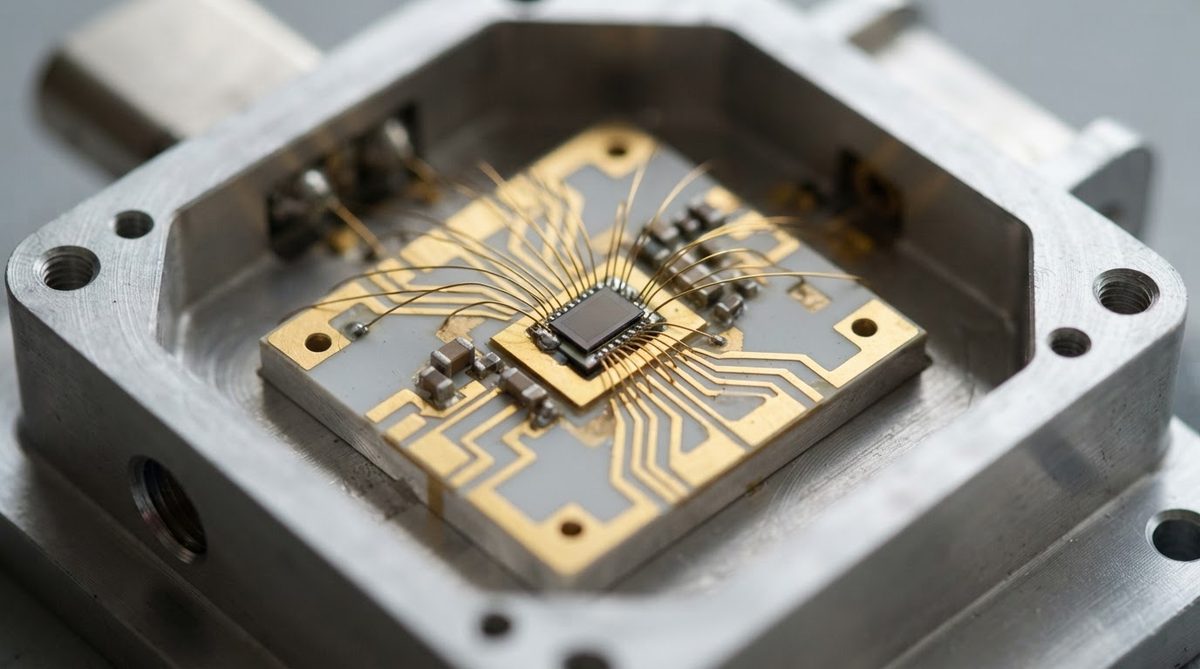
CTE mismatch between substrate and die is a leading cause of solder-joint cracking in thermal cycling. AlN at 4.5 ppm/°C sits close to silicon (2.6 ppm/°C), SiC (4.0 ppm/°C), and GaN-on-SiC. FR-4’s in-plane CTE of 14–17 ppm/°C creates a mismatch of 11–14 ppm/°C against silicon. Over thousands of thermal cycles (per JEDEC JESD22-A104), that mismatch accumulates plastic strain in solder joints. For die-attach reliability in automotive or aerospace power modules, this CTE advantage is often the deciding factor in the aluminum nitride AlN vs FR4 debate.
Cost Perspective
AlN raw substrate pricing runs roughly $8–$25 per 25 × 25 mm piece in quantities of 100, before metallisation. DBC or DPC metallisation adds $5–$35 depending on copper thickness and circuit complexity. A comparable FR-4 coupon with copper and solder mask costs under $1. The cost ratio narrows somewhat at smaller sizes (5 × 5 mm AlN coupons for individual die attach can be under $3 each at volume), but AlN never approaches FR-4 pricing. The economic justification for aluminum nitride AlN vs FR4 is always that the thermal or electrical performance cannot be achieved any other way. For a broader cost picture, see the ceramic vs MCPCB cost comparison.
Frequently Asked Questions
Can I solder components to AlN the same way I solder to FR-4?
Yes, but the metallisation must be compatible. AlN substrates metallised with DPC (Ti/Cu) or DBC (direct-bonded copper) accept standard SAC305 reflow soldering. Bare AlN ceramic is not solderable—it requires a metallised surface first. Reflow profiles are similar to FR-4, though ramp rates should be controlled to avoid thermal shock to the ceramic.
Does AlN need conformal coating?
AlN is hydrolytically sensitive: prolonged exposure to moisture degrades the surface. Most commercial AlN substrates include a passivation or oxidation layer that provides adequate protection for normal electronics environments. In high-humidity or condensing conditions, conformal coating or hermetic packaging is recommended. FR-4 is more moisture-tolerant without additional protection.
Is AlN safe to handle in a normal lab?
AlN substrates are non-toxic in solid form. Unlike beryllium oxide, AlN dust does not pose a carcinogenic hazard. Standard ceramic-handling precautions apply: wear gloves to avoid contaminating the surface, and use dust extraction if grinding or laser-cutting.
What is the maximum frequency where FR-4 is still acceptable?
FR-4 loss tangent (0.015–0.025 at 1 GHz) makes it marginal above roughly 3–5 GHz for most signal chains. Above 10 GHz, losses become severe and phase stability degrades. AlN, Rogers laminates, or LTCC are typical alternatives at these frequencies. The choice among them depends on whether you also need the thermal performance AlN provides.
Can I prototype on FR-4 and move to AlN for production?
You can prototype the circuit topology on FR-4 to validate logic and basic function, but thermal and RF performance will not transfer. Trace impedances change because εr differs (4.4 vs 8.8), and thermal margins measured on FR-4 are meaningless for an AlN production board. Plan at least one AlN prototype spin before committing to production.
Next Step
If your design involves die-level power dissipation above 2 W/cm², operating temperatures beyond FR-4’s Tg, or frequencies above 5 GHz, AlN is worth quoting. Start by comparing your requirements against the ceramic substrate options available, then request a quote with your Gerber files and thermal specs to get project-specific pricing.