The aluminum nitride AlN dielectric constant (εr) is 8.0–9.0 at 1 MHz, with a loss tangent (tan δ) of 0.0003–0.001 at the same frequency. These values make AlN a strong candidate for power electronics and RF substrates where low dielectric loss and high thermal conductivity (170–200 W/mK) are both required. The exact aluminum nitride AlN dielectric constant depends on grain size, purity, sintering aids, and measurement frequency.
Key Takeaways
- The aluminum nitride AlN dielectric constant ranges from 8.0 to 9.0 at 1 MHz, dropping slightly at higher frequencies (typically 8.3–8.8 at 10 GHz).
- Loss tangent for high-purity AlN stays below 0.001 up to at least 10 GHz, which is low enough for most microwave circuits.
- AlN’s thermal conductivity of 170–200 W/mK at 25 °C is roughly 6–8× that of 96% alumina, letting substrates handle higher power densities without separate heatsinking.
- Dielectric strength exceeds 15 kV/mm (per ASTM D149), providing adequate isolation for power modules up to several kilovolts.
- Higher εr than alumina (9.0–9.8 at 1 MHz) means slightly wider traces for a given impedance, but the difference is small enough that most layouts transfer directly.
What Determines the Aluminum Nitride AlN Dielectric Constant?
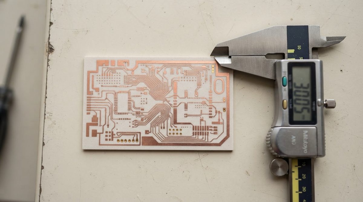
AlN is a wurtzite-structure III-V ceramic. Its ionic and covalent bonding produces a moderate permittivity — higher than PTFE-based laminates (εr ≈ 2–3) but lower than barium titanate ceramics (εr > 1 000). Three factors shift the aluminum nitride AlN dielectric constant within the 8.0–9.0 window:
Purity and sintering aids. Yttria (Y₂O₃) is the most common sintering aid for AlN. At 3–5 wt% Y₂O₃, grain-boundary phases form yttrium aluminate compounds that can nudge εr upward by 0.2–0.5 compared with a theoretical pure crystal. Higher-purity AlN grades with minimal secondary phases tend toward the lower end of the range.
Frequency. AlN’s permittivity is relatively flat from 1 kHz to 10 GHz, but ionic polarisation contributions diminish at microwave frequencies. Published data from Kyocera (SN-240 grade) shows εr ≈ 8.6 at 1 MHz dropping to about 8.3 at 10 GHz. This mild dispersion simplifies broadband impedance modelling.
Temperature. The temperature coefficient of permittivity for AlN is roughly +100 to +150 ppm/°C. Over a 200 °C swing, that translates to a shift of roughly 2–3% in εr — significant for tightly tuned resonators, but negligible for most power-module isolation layers.
Enter your substrate material, thickness, and target frequency to see how the dielectric constant affects estimated impedance and thermal performance at elevated temperatures.
AlN Dielectric Properties Compared to Other Ceramic Substrates
| Parameter | AlN | Al₂O₃ 96% | Al₂O₃ 99.6% | Si₃N₄ | Unit | Condition |
|---|---|---|---|---|---|---|
| Dielectric constant (εr) | 8.0–9.0 | 9.0–9.5 | 9.7–9.9 | 7.5–8.5 | — | 1 MHz, 25 °C |
| Loss tangent (tan δ) | 0.0003–0.001 | 0.0001–0.0004 | 0.0001–0.0002 | 0.001–0.005 | — | 1 MHz, 25 °C |
| Dielectric strength | 15–17 | 10–15 | 15–20 | 10–15 | kV/mm | ASTM D149 |
| Thermal conductivity | 170–200 | 24–28 | 28–35 | 70–90 | W/mK | 25 °C |
| CTE | 4.4–4.7 | 6.5–7.0 | 6.5–7.0 | 2.7–3.2 | ppm/°C | 20–400 °C |
Typical values for commercially available material, for comparison only. Confirm against the datasheet for your specific grade. Sources: Kyocera SN-240 datasheet; CoorsTek ADS-996 datasheet; Maruwa AlN datasheet.
AlN sits between 96% alumina and silicon nitride (Si₃N₄) in permittivity. Its loss tangent is comparable to alumina at 1 MHz and only slightly higher at 10 GHz. The decisive advantage is thermal conductivity: AlN removes heat 6–8× faster than alumina, which matters far more than a small εr difference in most power and RF designs. For a broader comparison, see our overview of dielectric properties of ceramic substrates.
How the Aluminum Nitride AlN Dielectric Constant Affects Impedance and Trace Geometry
A higher εr shrinks wavelength inside the substrate and narrows the trace width needed for a given characteristic impedance. Because the AlN dielectric constant is moderate (8.0–9.0), trace geometries land between those required for low-εr organic laminates and high-εr alumina. Here is a worked example for a 50 Ω microstrip line at 10 GHz:
Worked Example: 50 Ω Microstrip on AlN vs. 96% Alumina
Using the Hammerstad–Jensen closed-form approximation for microstrip impedance:
- Substrate: AlN, εr = 8.5, thickness h = 0.635 mm
- Target Z₀: 50 Ω
- Calculated trace width (W): ≈ 0.56 mm
For the same geometry on 96% alumina (εr = 9.3), the 50 Ω trace width narrows to ≈ 0.49 mm. The 8–13% width difference is modest and well within standard DPC or thin-film metallisation tolerances. In practice, the choice between AlN and alumina for an RF line is almost never driven by trace width; it is driven by how much heat the substrate must conduct away from the die.
If your design requires thin AlN substrates (0.25 mm or less), recalculate impedance carefully — the reduced h compresses trace widths and tightens the tolerance budget.
Frequency-Dependent Behaviour: Does AlN Work at mmWave?
Published measurements (e.g., Kuo et al., IEEE Trans. Microwave Theory and Techniques, 2005) show the aluminum nitride AlN dielectric constant remains within ±3% of its 1 MHz value up to 40 GHz. Loss tangent rises gradually, reaching approximately 0.002–0.004 by 30 GHz depending on grain size and porosity. That is adequate for power-amplifier matching networks and antenna feed structures, but it is higher than low-loss PTFE laminates (tan δ < 0.001 at 30 GHz) or fused silica (tan δ ≈ 0.0001).
For pure signal-path mmWave applications above 30 GHz where loss is the primary concern, quartz or PTFE-based substrates typically win. AlN earns its place when the circuit also dissipates significant heat — GaN-on-AlN power amplifier modules at 5G frequencies are the canonical example.
When Not to Use AlN for Its Dielectric Properties
Low-frequency, low-power digital boards. If you need isolation but not thermal performance, 96% alumina costs 3–5× less per unit area and has comparable dielectric strength. FR-4 costs even less.
Ultra-low-loss RF above 30 GHz. Fused quartz (εr ≈ 3.8, tan δ < 0.0001) or Rogers RO3003 (εr ≈ 3.0, tan δ ≈ 0.001) will give you lower insertion loss per unit length. Choose AlN only if the thermal load demands it.
Large-area boards (> 150 mm × 150 mm). AlN substrates are limited in panel size and are brittle. For large-format RF boards, organic laminates with thermal vias or metal-core PCBs are more practical.
Cost-sensitive consumer products. AlN substrates are a premium material. If the application does not require thermal conductivity above 30 W/mK or operation above 300 °C, alumina or MCPCB is almost always the better economic choice.
Practical Design Tips for AlN Dielectric Layers
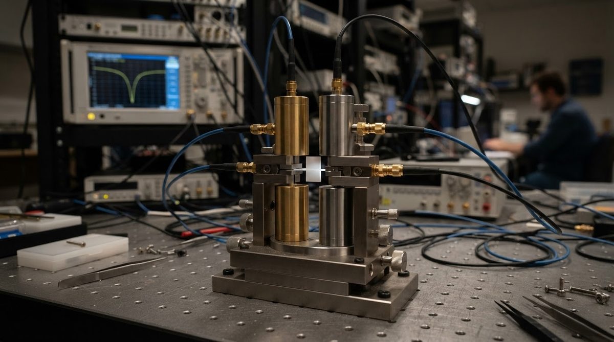
Request εr data at your operating frequency. Substrate vendors measure at 1 MHz by default. If your circuit operates at 5 GHz or above, ask for data at that frequency or measure a test coupon yourself using a split-post dielectric resonator (per IEC 61189-2-721).
Account for metallisation roughness. DPC (direct plated copper) on AlN can have surface roughness Ra of 0.3–0.8 µm. At frequencies above 10 GHz, conductor loss from surface roughness often exceeds dielectric loss, making tan δ less critical than metallisation quality.
Match CTE to your die. AlN’s CTE of 4.4–4.7 ppm/°C closely matches silicon (2.6 ppm/°C) and GaN-on-SiC (≈ 4.0 ppm/°C), reducing solder-joint fatigue. For more on this, see CTE matching in ceramic PCB design.
FAQ
Does the aluminum nitride AlN dielectric constant change with substrate thickness?
No. Permittivity is a bulk material property and does not depend on thickness. However, thinner substrates increase capacitance per unit area and change the effective dielectric constant seen by a microstrip line, which affects impedance.
Can I use standard EM simulators with AlN?
Yes. Tools like Ansys HFSS, Keysight ADS, and Sonnet accept user-defined εr and tan δ. Enter the values at your target frequency from the substrate vendor’s datasheet, not the 1 MHz default.
Is AlN’s loss tangent low enough for 5G base-station filters?
For sub-6 GHz 5G bands, AlN’s tan δ of 0.001–0.002 is acceptable for matching networks and combiners. For narrow-band cavity filters requiring Q > 5 000, sapphire or low-loss alumina (99.6%) is a better fit.
How does moisture affect AlN’s dielectric properties?
AlN can hydrolyse in humid environments, forming aluminum hydroxide on the surface. This degradation raises surface conductivity and can increase effective loss tangent. Sealed packaging or a passivation layer (e.g., sputtered SiO₂) prevents this. For the full AlN material properties and handling guidance, see our datasheet page.
What test standard should I specify for incoming εr inspection?
IEC 60250 (or the equivalent ASTM D150) covers permittivity and loss tangent measurement for solid insulating materials. Specify the test frequency, temperature, and sample geometry in your purchase order to get comparable results across lots.
Next Step
If you are designing an RF or power circuit on AlN and need substrates with verified dielectric data, request a quote with your target frequency and impedance requirements. We supply AlN substrates in multiple grades and thicknesses, with DPC metallisation available. Visit our AlN ceramic PCB wholesale page or go directly to our instant quote form to start.