Substrate Definition in PCB Engineering
The substrate definition in printed circuit board design is straightforward: a substrate is the rigid or flexible insulating base material that mechanically supports components and electrically isolates conductive layers from one another. Every PCB has at least one substrate layer. The substrate’s material determines the board’s thermal, electrical, and mechanical performance limits. Understanding this substrate definition is essential before selecting a material for any new design.
Common Substrate Materials Compared
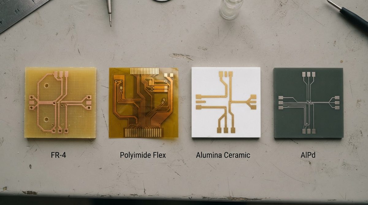
The table below compares the most widely used substrate families. Property ranges reflect typical commercial grades; always confirm values against the specific manufacturer’s datasheet.
| Material | Thermal Conductivity (W/m·K) | Dielectric Constant (1 MHz) | Max Continuous Temp (°C) | Typical Use |
|---|---|---|---|---|
| FR-4 (glass-epoxy) | 0.25–0.35 | 4.2–4.7 | 130–140 | General electronics |
| Polyimide (flex) | 0.12–0.35 | 3.2–3.5 | 250–300 | Flex circuits, aerospace |
| Metal-core (Al base) | 1–3 (dielectric layer) | 4–6 | 130–150 | LED lighting |
| Al₂O₃ 96% | 24–28 | 9.4–9.8 | 1 600+ | Power modules, RF |
| AlN | 170–200 | 8.6–8.9 | 1 000+ | High-power semiconductors |
| Si₃N₄ | 70–90 | 8.0–8.5 | 1 000+ | EV inverters, high-reliability |
Typical values for commercially available material, for comparison only. Confirm against the datasheet for your specific grade.
Organic substrates like FR-4 are inexpensive and easy to process but limited in thermal conductivity and operating temperature. Ceramic substrates cost more per unit area yet handle far higher heat flux and operate at temperatures where organics decompose. The substrate definition stays the same regardless of material class; what changes is the envelope of performance the substrate can deliver.
Key Properties That Define Substrate Performance
Once you have a clear substrate definition, the next step is evaluating which properties matter most for your application. The following parameters separate one substrate material from another:
- Thermal conductivity — controls how fast heat moves through the substrate away from a component. Higher values mean lower thermal resistance for the same geometry, directly reducing junction temperature.
- Dielectric strength and constant — determine how much voltage the substrate can withstand and how it affects signal impedance. Ceramic substrates typically offer dielectric strengths above 10 kV/mm (per ASTM D149), making them suitable for high-voltage isolation.
- Coefficient of thermal expansion (CTE) — must be close to the CTE of the die or component soldered to it. Alumina’s CTE of roughly 7 ppm/°C is a closer match to silicon (≈ 3–4 ppm/°C) than FR-4’s 14–17 ppm/°C, reducing solder-joint fatigue over thermal cycles.
- Surface roughness — affects conductor adhesion and high-frequency signal loss. Ceramic substrates can be lapped or polished to Ra values below 0.1 µm when thin-film metallisation is required.
Enter your substrate material, thickness, and dissipated power below to see how these properties translate into an estimated temperature rise for your specific design.
When a Ceramic Substrate Is Not the Right Choice
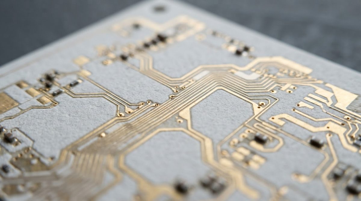
If the board runs below 100 °C, dissipates modest heat, and needs complex multilayer routing at low cost, FR-4 is almost always the better option. Ceramic substrates are brittle, limited in maximum panel size, and significantly more expensive. Choose ceramic only when thermal, frequency, voltage, or reliability requirements exceed what organic laminates can deliver.
For guidance on selecting among alumina, aluminum nitride, and silicon nitride, see how to choose the right ceramic substrate.
Frequently Asked Questions
Is a substrate the same thing as a PCB?
No. The substrate is one layer within a PCB — the insulating base. A finished PCB includes the substrate plus patterned conductors, plated vias, solder mask, and surface finish. The substrate definition refers only to the dielectric base material itself.
Can I use multiple substrate materials in one board?
Yes. Hybrid constructions bond a ceramic substrate to an organic or metal-core carrier. This approach places high-performance ceramic only where it is needed, keeping overall cost down. The trade-off is added assembly complexity and potential CTE mismatch at the bond interface.
How does substrate choice affect high-frequency performance?
The substrate’s dielectric constant and loss tangent directly set signal propagation speed and insertion loss. Low-loss ceramics like alumina (tan δ ≈ 0.0001–0.0003 at 10 GHz) outperform FR-4 (tan δ ≈ 0.015–0.025) by orders of magnitude, which matters above roughly 1 GHz.
Does the substrate definition change for flex circuits?
The core definition stays the same — it is still the insulating base that supports conductors. In flex circuits the substrate is a thin polyimide film (typically 12.5–50 µm) instead of a rigid laminate or ceramic. The mechanical flexibility is a property of the material, not a change in what the substrate does.