Thermal Conductivity Definition
The thermal conductivity definition used in PCB engineering is straightforward: thermal conductivity (symbol k or λ) is the rate at which heat passes through a material per unit area for a given temperature gradient. It is measured in watts per metre-kelvin (W/mK) and tested per ASTM E1461 (laser flash) or ASTM C408 (guarded hot plate). A higher value means the material moves heat away from a source faster.
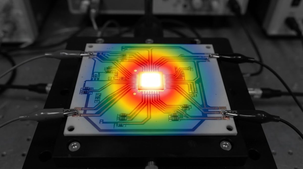
In PCB design, the substrate’s thermal conductivity determines how effectively heat spreads from a component pad to a heat sink or ambient air. This property is one input to calculating thermal resistance across a substrate; the other inputs are thickness and cross-sectional area. Understanding the thermal conductivity definition and how it applies to your specific substrate is the first step in any serious thermal design.
Typical Thermal Conductivity Values for Ceramic Substrates
| Material | Thermal conductivity (W/mK) | Condition | Source |
|---|---|---|---|
| FR-4 (reference) | 0.25–0.35 | 20 °C, through-plane | IPC-4101 datasheets |
| Al₂O₃ 96% | 24–28 | 20 °C | CoorsTek ADS-96R datasheet |
| Al₂O₃ 99.6% | 28–35 | 20 °C | Kyocera A-493 datasheet |
| AlN | 170–200 | 20 °C | Maruwa AN series datasheet |
| Si₃N₄ | 70–90 | 20 °C | Kyocera SN series datasheet |
Typical values for commercially available material, for comparison only. Confirm against the datasheet for your specific grade.
Even 96% alumina at 24–28 W/mK conducts heat roughly 80–100× better than FR-4. AlN pushes that advantage to nearly 600×. For a full side-by-side comparison of ceramic grades, see the ceramic thermal conductivity table.
Why Thermal Conductivity Matters in Board Design
Thermal conductivity sets the upper limit on how much power a substrate can conduct away before junction temperatures rise past safe limits. A 1 mm thick, 10 × 10 mm alumina 96% pad carrying 5 W produces a through-thickness ΔT of roughly 1.8–2.1 °C. The same geometry in FR-4 yields ΔT ≈ 143–200 °C—well beyond any practical operating window.
However, thermal conductivity is not the only factor. Substrate thickness, copper layer coverage, and the interface between ceramic and heat sink all contribute to total thermal resistance. A thin, well-bonded alumina board can outperform a thicker AlN board with a poor thermal interface.
Key variables that interact with thermal conductivity in a real design:
- Substrate thickness — thinner substrates reduce thermal resistance proportionally, even at the same thermal conductivity.
- Copper coverage and weight — copper at ~390 W/mK spreads heat laterally before it enters the ceramic.
- Thermal interface material (TIM) — a poor TIM layer can bottleneck the path regardless of substrate conductivity.
- Ambient and forced-convection conditions — high airflow reduces the heat-sink-to-air resistance, making substrate conductivity a larger share of the total.
Enter your substrate material, thickness, and dissipated power below to see how thermal conductivity affects junction temperature rise in your specific layout.
Frequently Asked Questions
What does thermal conductivity definition mean in simple terms?
The thermal conductivity definition describes how many watts of heat flow through one metre of material for every degree of temperature difference across it. In practical PCB terms, a substrate with 25 W/mK moves heat 100× faster than one at 0.25 W/mK. The unit is always W/mK, and higher is better for heat removal.
Does thermal conductivity change with temperature?
Yes. Most ceramics see a gradual decrease in thermal conductivity as temperature rises. AlN, for example, drops from ~180 W/mK at 20 °C to roughly 120–140 W/mK at 300 °C (per Maruwa datasheets). Always check the datasheet curve for your operating range rather than relying on a single room-temperature value.
Is thermal conductivity the same as thermal diffusivity?
No. Thermal conductivity measures steady-state heat flow, while thermal diffusivity (measured in mm²/s) describes how quickly a material reaches thermal equilibrium during transient events. Both are derived from the same laser-flash test (ASTM E1461), but they answer different design questions. For pulsed-power applications, diffusivity matters more than conductivity alone.
Can I compare thermal conductivity values from different datasheets directly?
Only if the test method and temperature are the same. A value measured by laser flash (ASTM E1461) at 20 °C is not directly comparable to a guarded-hot-plate result (ASTM C408) at 100 °C. Always note the test standard and temperature condition before placing two materials side by side.
Related Terms
Browse more entries in the ceramic PCB glossary, including thermal resistance, CTE, and dielectric strength.