A wire bonding service on ceramic substrates produces more reliable interconnects than bonding on organic boards because ceramics stay dimensionally stable through the thermal cycles and ultrasonic energy the process demands. Alumina (Al₂O₃) and aluminum nitride (AlN) substrates paired with gold or aluminum metallization consistently achieve bond pull strengths above 3 gf for 25 µm gold wire and above 7 gf for 300 µm aluminum ribbon, meeting MIL-STD-883 Method 2011 requirements with margin.
Key Takeaways
- Gold ball bonding on ceramic substrates typically achieves pull strengths of 6–12 gf for 25 µm wire, well above the MIL-STD-883 minimum of 3 gf.
- Aluminum wedge bonding handles higher currents and is standard for power modules; 300–500 µm Al ribbon on DBC or AMB substrates carries 10–50 A per bond.
- Bond pad metallization must be matched to wire type: gold or nickel/gold for Au wire, bare aluminum or nickel/palladium/gold for Al wire.
- Ceramic substrates eliminate pad-lift failures common on organic laminates because the metal-to-ceramic adhesion (often >6 MPa peel strength per ASTM D3359) exceeds the wire bond’s own failure load.
- Surface roughness of the bond pad matters more than most engineers expect; Ra of 0.1–0.5 µm is the practical window for consistent thermosonic bonding.
Wire Bonding Methods Used on Ceramic Substrates
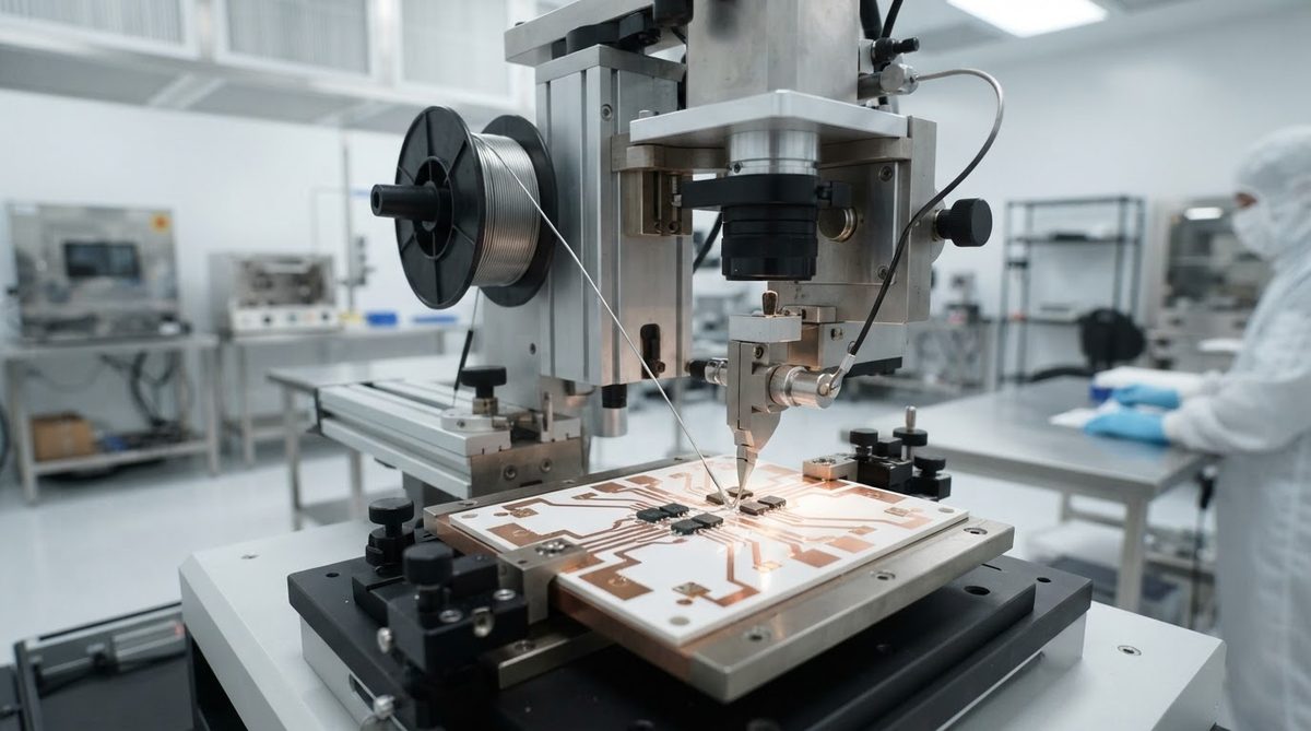
Two methods dominate commercial wire bonding on ceramics: thermosonic ball bonding and ultrasonic wedge bonding. A third method, thermocompression bonding, still appears in hermetic packaging but is slower and largely replaced by thermosonic processes.
Thermosonic Ball Bonding
A capillary tool forms a free-air ball on gold wire (typically 18–33 µm diameter), then presses and ultrasonically scrubs it onto a heated bond pad at 150–220 °C. The ball bond lands on the die pad; the stitch (wedge) bond lands on the substrate pad. This method is fast—8–15 bonds per second on modern equipment—and the ball shape tolerates angular misalignment, making it forgiving for hybrid circuit layouts.
Gold wire is expensive. At roughly $55–65 per troy ounce (mid-2025), material cost matters for high-pin-count devices. Copper ball bonding is an alternative on lead frames but is rarely used on ceramic substrates because the harder copper ball risks cracking brittle ceramic surfaces under bonding force.
Ultrasonic Aluminum Wedge Bonding
A wedge tool presses aluminum wire or ribbon onto the pad at room temperature (or mildly heated to 25–150 °C) using ultrasonic energy alone. Wedge bonding is directional—the wire exits along the tool axis—so layout must account for bond orientation. Aluminum wedge bonds are standard in power electronics because Al wire is cheap, carries high current, and bonds well to aluminum-metallized die pads without intermetallic concerns.
Bond Pad Metallization Requirements
The metallization stack on your metallized ceramic substrate determines whether bonding succeeds or fails. The table below summarizes proven combinations.
| Wire Material | Recommended Pad Metallization | Typical Bond Pad Thickness | Notes |
|---|---|---|---|
| Au (25 µm) | Ni/Au (electrolytic or electroless) | Au: 0.5–1.5 µm over 2–5 µm Ni | Au thickness <0.3 µm risks Kirkendall voids at Ni interface |
| Au (25 µm) | Thick-film Au (fired) | 5–15 µm | Excellent adhesion to Al₂O₃; surface roughness must be controlled |
| Al (25–500 µm) | Ni/Pd/Au (thin Au flash ≤0.05 µm) | Au flash: ≤0.05 µm; Pd: 0.05–0.15 µm; Ni: 2–5 µm | Thick Au under Al wire causes Au-Al intermetallics (“purple plague”) |
| Al (25–500 µm) | Bare Al (sputtered or evaporated) | 1–4 µm | Monometallic system; no intermetallic risk; oxidation must be controlled |
| Cu (25 µm) | Not recommended on ceramic | — | High bonding force risks ceramic fracture |
Typical values for commercially available materials, for comparison only. Confirm against the datasheet for your specific grade.
A common mistake is specifying standard ENIG (electroless nickel / immersion gold) for gold wire bonding. Immersion gold is typically only 0.05–0.1 µm thick, which is fine for soldering but too thin for reliable thermosonic ball bonding. Electrolytic gold plating of 0.5 µm minimum is the usual specification. If your substrate uses gold-metallized ceramic with thick-film Au, bonding is straightforward because adhesion and thickness are already in range.
Design Rules for Wire-Bondable Ceramic Pads
Pad geometry, spacing, and surface condition drive bond yield. The rules below apply to most commercial wire bonders (Kulicke & Soffa, Hesse, ASM Pacific) operating on alumina or AlN substrates.
- Minimum pad size: 100 × 100 µm for 25 µm Au ball bonding (ball diameter ~60–75 µm); 400 × 400 µm for 300 µm Al wedge bonding.
- Pad pitch: ≥150 µm center-to-center for 25 µm Au wire; ≥600 µm for 300 µm Al wire.
- Surface roughness: Ra 0.1–0.5 µm. Below 0.1 µm the tool can skid; above 0.5 µm the ball deforms unevenly and pull strength drops.
- Pad coplanarity: ≤25 µm across the bonding area. Ceramic substrates help here—fired alumina flatness is typically ±25 µm over 25 mm, far better than FR-4.
- Contamination: Organic residue >1 monolayer degrades bond shear strength by 30–50%. Plasma cleaning (O₂ or Ar, 100–300 W, 2–5 min) immediately before bonding is standard practice.
For detailed layout guidance on pad geometry and routing, see the guide on wire-bondable ceramic PCB design.
Worked Example: Pull Strength Verification
Suppose you are bonding 25 µm gold wire to Ni/Au pads on a 96% alumina substrate. MIL-STD-883 Method 2011, Condition D requires a minimum destructive pull strength of 3.0 gf for 25 µm Au wire.
After bonding 100 wires, you destructive-pull-test a sample of 10 per the standard. Results: mean pull strength = 8.2 gf, minimum individual = 5.9 gf, standard deviation = 1.1 gf. All 10 exceed the 3.0 gf minimum. The failure mode is wire neck break (not ball lift or pad lift), which is the desired failure mode—it means the bond interface is stronger than the wire itself.
If you see ball-lift or pad-lift failures, investigate metallization adhesion, surface contamination, or excessive bonding force. Ball lift on thick-film gold often indicates under-fired paste (firing temperature too low by 20–50 °C reduces glass-frit bonding to the ceramic).
Why Ceramic Substrates Outperform Organic Boards for Wire Bonding
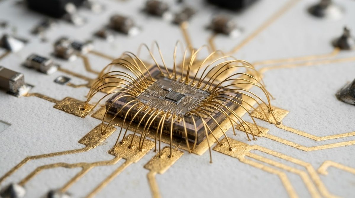
Organic laminates like FR-4 and polyimide flex have three problems for wire bonding. First, their glass transition temperature (Tg = 130–260 °C depending on resin) limits the stage temperature available for thermosonic bonding. Second, the CTE mismatch between copper traces and the laminate causes pad shift during thermal cycling, stressing wire bonds. Third, outgassing from the resin contaminates bond pads in hermetic packages.
Ceramic substrates avoid all three. Al₂O₃ is stable to over 1,600 °C. Its CTE (6.5–7.2 ppm/°C for 96% alumina, per CoorsTek datasheet) closely matches silicon (2.6 ppm/°C) and GaAs (5.7 ppm/°C), reducing thermomechanical stress on bonds. Outgassing is negligible. These properties make ceramics the default substrate for wire-bonded hybrid circuits in aerospace, medical implants, and high-reliability power modules.
When Not to Use Ceramic for Wire Bonding
Ceramic substrates add cost. If your application does not need high-temperature stability, hermeticity, or CTE matching to a semiconductor die, consider alternatives. Standard lead frames with wire bonding are far cheaper for high-volume consumer ICs. Organic substrates with flip-chip or solder-bump interconnects eliminate wire bonding entirely and offer higher I/O density. If your device operates below 125 °C, sees no thermal cycling, and is not in a hermetic package, the cost premium of ceramic is hard to justify for wire bonding alone.
Also consider that ceramic is brittle. Drop-shock environments (handheld consumer electronics) may favor organic substrates with wire bonding or flip-chip, where the board absorbs impact energy through flexure rather than fracture.
Frequently Asked Questions
Can you wire bond directly to a bare ceramic substrate?
No. Wire bonding requires a metallic pad. The ceramic must be metallized first using thick-film printing, thin-film sputtering, DBC, or DPC processes. The metallization provides the ductile surface needed for ultrasonic scrubbing to form a bond.
What pull strength should I specify for wire bonds on ceramic?
For 25 µm gold wire, MIL-STD-883 Method 2011 requires a minimum destructive pull of 3.0 gf. Most ceramic-substrate bonds exceed this by 2–3×. Specify both a minimum individual value and a mean, and require wire-neck-break as the dominant failure mode.
Does aluminum wire bonding damage ceramic substrates?
Heavy aluminum wire (300–500 µm) requires bonding forces of 500–2,000 gf, which can crack thin ceramic substrates. Use substrates at least 0.38 mm thick for heavy Al wire, and ensure the substrate is fully supported by the bonding stage with no voids underneath. Alumina at 96% purity has a flexural strength of 300–380 MPa (per ASTM C1161), which is adequate if the pad area is properly backed.
How does substrate flatness affect wire bond yield?
Substrate bow or warp greater than 50 µm across the bonding area causes inconsistent bonding force, leading to non-sticks or overbonded (cratered) pads. Ceramic substrates fired to standard tolerances typically hold ±25 µm flatness over 25 mm, which is well within the capability of modern autobonders. Verify incoming flatness if your blank ceramic substrates are large panels that will be singulated after bonding.
Is gold or aluminum wire better for high-temperature operation?
Gold wire bonds are stable to roughly 300 °C in inert atmosphere. Aluminum wire bonds degrade above 175–200 °C due to oxidation and intermetallic growth at Al-Au interfaces (if bonded to gold pads). For sustained operation above 200 °C, use gold wire on gold pads or aluminum wire on aluminum pads to avoid bimetallic intermetallic compounds.
Next Step
If you are specifying a ceramic substrate for wire bonding, start with the metallization and pad geometry. Review the ceramic PCB design guidelines to confirm your layout is compatible with your bonding process, then request a quote with your pad metallization and wire type clearly noted in the fabrication drawing.