An alumina 96% Al2O3 HTCC co-fired ceramic substrate is a multilayer ceramic board formed by co-firing alumina green tape with refractory metallization (tungsten or molybdenum-manganese) at 1,500–1,600 °C. It is the most widely used ceramic substrate grade in electronics, balancing adequate thermal conductivity (24–28 W/mK), high mechanical strength, and moderate cost relative to higher-purity or specialty ceramics. For engineers evaluating alumina 96% Al2O3 HTCC co-fired ceramic for a new design, the sections below cover properties, process steps, trade-offs, and the cases where a different material is the better call.
Key Takeaways
- Thermal conductivity of 96% alumina HTCC substrates is 24–28 W/mK at 25 °C, per CoorsTek ADS-96R and Kyocera A-473 datasheets.
- Firing temperature of 1,500–1,600 °C restricts internal conductors to refractory metals—tungsten (W) or moly-manganese (Mo-Mn)—not copper or silver.
- Flexural strength ranges from 330–380 MPa (ASTM C1161, 4-point bend), making 96% alumina tougher than most LTCC tapes.
- Dielectric constant is 9.0–9.5 at 1 MHz (25 °C), which matters for RF impedance calculations.
- Cost per unit area is roughly 30–50% lower than 99.6% alumina HTCC, making it the default choice unless purity-driven performance is required.
What Is Alumina 96% Al2O3 HTCC Co-Fired Ceramic?
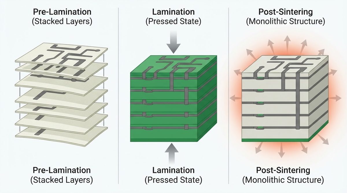
HTCC (High-Temperature Co-fired Ceramic) is a process in which unfired ceramic tape layers are stacked, laminated, and sintered together above 1,400 °C. The “co-fired” label means that internal metallization—via fills, traces, ground planes—sinters at the same time as the ceramic body, forming a monolithic structure. When the base material is 96% purity alumina, the result is an alumina 96% Al2O3 HTCC co-fired ceramic package that combines hermetic sealing with embedded multilayer interconnects.
The defining trade-off versus alumina 96% LTCC substrates is metallization choice. LTCC fires below 1,000 °C, so it can use silver or gold conductors with low resistivity (1.6–2.4 µΩ·cm). HTCC must use tungsten (5.6 µΩ·cm) or Mo-Mn, which means higher trace resistance. For power distribution and hermetic packaging this is acceptable; for high-frequency signal routing where conductor loss dominates, LTCC or thin-film approaches may be better.
Material Properties of Alumina 96% Al2O3 HTCC Co-Fired Ceramic
| Parameter | Value | Unit | Condition | Source |
|---|---|---|---|---|
| Al2O3 purity | 96 | % | — | CoorsTek ADS-96R |
| Thermal conductivity | 24–28 | W/mK | 25 °C | CoorsTek ADS-96R |
| Dielectric constant (εr) | 9.0–9.5 | — | 1 MHz, 25 °C | Kyocera A-473 |
| Dielectric strength | 14–17 | kV/mm | AC, 60 Hz | CoorsTek ADS-96R |
| Flexural strength | 330–380 | MPa | ASTM C1161, 4-pt | CoorsTek ADS-96R |
| CTE | 7.1–7.4 | ppm/°C | 25–300 °C | Kyocera A-473 |
| Volume resistivity | >1014 | Ω·cm | 25 °C | CoorsTek ADS-96R |
| Max continuous use temp | 1,600 | °C | in inert/vacuum | CoorsTek |
| Density | 3.72–3.78 | g/cm³ | — | CoorsTek ADS-96R |
Typical values for commercially available material, for comparison only. Confirm against the datasheet for your specific grade.
Enter your substrate dimensions, material grade, and power dissipation below to estimate the temperature rise through an alumina 96% Al2O3 HTCC co-fired ceramic layer.
HTCC Co-Firing Process Overview
- Tape casting. Alumina powder, binder, and plasticizer are cast into thin green sheets (0.1–1.0 mm typical).
- Via punching. Mechanical or laser punching creates through-holes for interlayer connections.
- Metallization. Tungsten or Mo-Mn paste is screen-printed onto each layer for traces and via fills.
- Stacking and lamination. Layers are aligned, stacked, and pressed under heat (60–80 °C) and pressure (20–30 MPa) to bond the green tapes.
- Burnout. Organic binders are removed in a slow ramp to ~500 °C.
- Sintering. The laminate fires at 1,500–1,600 °C in a hydrogen or forming-gas atmosphere, densifying the ceramic and metallization simultaneously.
- Post-fire plating. Nickel and gold are plated over exposed tungsten pads to enable soldering or wire bonding.
Shrinkage during sintering is typically 15–20% in X-Y and Z. Tight dimensional control requires well-characterized shrinkage data and matched lot-to-lot powder consistency.
When 96% Alumina HTCC Is the Right Choice
This substrate fits best in hermetic packages, sensor housings, and multilayer interconnect structures where you need moderate thermal performance, good mechanical strength, and the ability to embed internal conductors and vias in a monolithic ceramic body. Common applications include automotive sensor packages (exhaust-gas and pressure sensors), military hybrid microelectronics, and high-reliability LED submounts.
If your design requires thermal conductivity above 100 W/mK, consider aluminum nitride thick film substrates instead. If you need the lowest possible conductor resistance for RF signal integrity, LTCC with silver metallization or thin-film alumina is a better match. And where higher purity improves IR transparency or reduces dielectric loss at mmWave frequencies, 99.6% alumina HTCC substrates are worth the cost premium.
Worked Example: Thermal Resistance of an Alumina 96% Al2O3 HTCC Co-Fired Ceramic Substrate
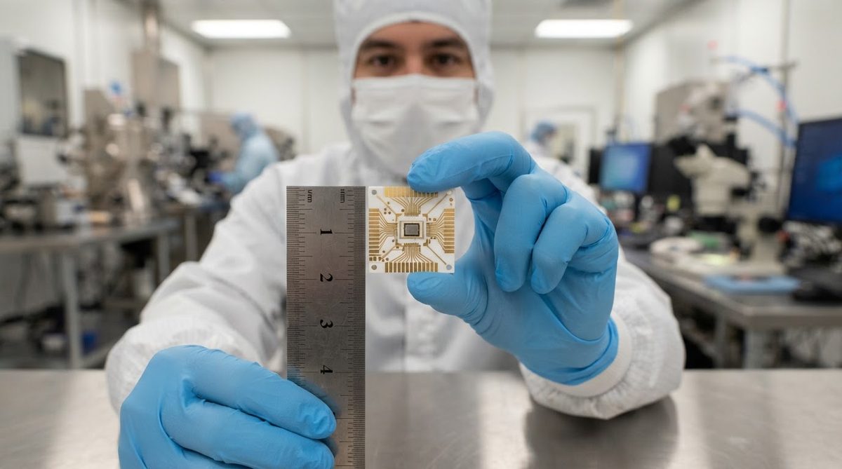
Suppose you have a 10 mm × 10 mm die mounted on a 96% alumina HTCC substrate that is 0.635 mm thick. The one-dimensional thermal resistance through the substrate is:
Rth = t / (k × A)
Where t = 0.635 × 10⁻³ m, k = 26 W/mK (mid-range), A = 10 × 10 × 10⁻⁶ m² = 1 × 10⁻⁴ m².
Rth = 0.000635 / (26 × 0.0001) = 0.244 °C/W.
At 5 W dissipation, the temperature drop across the substrate alone is about 1.2 °C—negligible in most designs. The real thermal bottleneck is usually the die-attach layer and the interface to the heat sink, not the ceramic itself.
When Not to Use 96% Alumina HTCC
Choose a different substrate if any of these apply:
- High-frequency signal routing above ~20 GHz. Tungsten’s resistivity increases conductor loss significantly. LTCC with silver or 99.6% alumina thin film offers lower loss.
- High heat flux (>50 W/cm²). AlN (170–200 W/mK) or Si3N4 DBC handles the thermal load better.
- Cost-sensitive, non-hermetic consumer products. FR-4 or metal-core PCBs cost a fraction of HTCC and are sufficient for most consumer electronics.
- Large panel sizes. HTCC shrinkage control becomes difficult above ~150 mm; for large-area substrates, post-fired thick film on pre-sintered alumina is simpler.
Standard Substrate Sizes and Custom Options
Finished alumina 96% Al2O3 HTCC co-fired ceramic substrates are commonly available in standard ceramic substrate sizes such as 2″ × 2″ (50.8 × 50.8 mm) and 4.5″ × 4.5″ (114.3 × 114.3 mm), with custom shapes cut by laser or diamond scribing after sintering. Thickness after firing ranges from 0.25 mm to several millimeters depending on the number of laminated layers.
Frequently Asked Questions
Can I use copper conductors in an HTCC substrate?
No. Copper melts at 1,085 °C, well below the 1,500–1,600 °C HTCC sintering temperature. HTCC uses tungsten or molybdenum-manganese for internal conductors. Copper can only be applied after firing, as a plated or brazed surface layer.
What is the CTE match between 96% alumina and silicon?
96% alumina has a CTE of 7.1–7.4 ppm/°C (25–300 °C), while silicon is about 2.6 ppm/°C. The mismatch is roughly 4.5–4.8 ppm/°C, which requires a compliant die-attach material (e.g., soft solder or silver-filled epoxy) to manage stress on large die. AlN (4.5 ppm/°C) is a closer CTE match to silicon.
How does 96% alumina HTCC compare to 96% thick film alumina?
Both use the same base ceramic, but HTCC embeds conductors inside the ceramic during firing, enabling true multilayer structures and hermetic via interconnects. 96% alumina thick film substrates print conductors onto a pre-sintered substrate surface and are limited to one or two metal layers without complex post-processing.
Is 96% alumina HTCC suitable for vacuum or space environments?
Yes. The ceramic is fully dense after sintering, with no organic content, and outgasses negligibly. Tungsten metallization is stable in vacuum to very high temperatures. HTCC packages have a long history in space-qualified hybrid circuits per MIL-PRF-38534.
What surface finish goes over exposed tungsten pads?
Nickel-gold (Ni/Au) plating is standard. A nickel barrier layer (3–8 µm) prevents gold-tungsten interdiffusion, and a gold layer (0.5–3 µm) provides solderability or wire-bond compatibility. Electroless nickel / immersion gold (ENIG) is also used for finer features.