Engineers asking how to drill ceramic substrate quickly discover that standard carbide or HSS bits are useless. Alumina (Al₂O₃) has a Vickers hardness of 14–16 GPa, and aluminum nitride (AlN) sits at 10–12 GPa—both destroy conventional tooling on contact. To drill holes in fired ceramic you need one of three post-fire methods (laser ablation, ultrasonic machining, or diamond-tool drilling), or you punch the holes before sintering in the green state. The right choice depends on hole diameter, positional tolerance, substrate thickness, and volume.
Why Standard Drill Bits Fail on Fired Ceramics
A 96% alumina substrate has a flexural strength of 300–380 MPa (per ASTM C1161, 4-point bend) and a fracture toughness of only 3.5–4.0 MPa·√m. That combination means the material is extremely hard but brittle. A spinning carbide bit generates point loads that nucleate cracks rather than cut chips. The bit dulls within seconds, and the substrate cracks or chips around the hole entry and exit. This is true for 96% alumina, 99.6% alumina, and aluminum nitride alike.
Even diamond-coated twist drills struggle below 0.3 mm diameter in fired alumina. The failure mode shifts from bit wear to substrate fracture: the drill’s thrust force exceeds the local compressive strength around the hole, and the exit side spalls. Every post-fire method for how to drill ceramic substrate addresses this by removing material thermally (laser), ultrasonically, or with controlled abrasive contact.
How to Drill Ceramic Substrate with Laser Ablation
Laser ablation is the most common method for vias and small through-holes in fired ceramic substrates. A pulsed UV or CO₂ laser vaporises material in successive passes. UV Nd:YAG lasers (355 nm) produce the cleanest holes in alumina; CO₂ lasers (10.6 µm wavelength) work well for AlN but leave a wider heat-affected zone (HAZ) in alumina.
Typical Capabilities
| Parameter | UV Nd:YAG (355 nm) | CO₂ (10.6 µm) | Unit |
|---|---|---|---|
| Minimum hole diameter | 50–80 | 100–150 | µm |
| Positional accuracy | ±10–15 | ±20–25 | µm |
| Max practical substrate thickness | 0.63 | 1.0 | mm |
| Heat-affected zone width | 5–15 | 20–50 | µm |
| Taper (entry vs. exit diameter) | 3–8% | 5–12% | of diameter |
| Throughput (0.3 mm holes, 0.38 mm substrate) | ~2–5 | ~5–10 | holes/sec |
Typical values for commercially available equipment. Confirm against your laser vendor’s process qualification data.
Laser-drilled holes in alumina exhibit a slight taper: the entry side is wider than the exit. For vias that will be metallised, a taper under 8% is generally acceptable. If your design requires straight-wall holes tighter than ±15 µm, laser drilling alone may not suffice—you may need a post-drill lapping or grinding step to true up the surface around the via.
Residue and cleaning. Laser ablation of AlN can produce aluminum oxide and aluminum oxynitride residues on the hole wall. These must be cleaned (typically ultrasonic bath in dilute HF or proprietary ceramic etchants) before metallisation, or adhesion of the via fill will be poor. For alumina, the recast layer is thinner but still present; a light etch improves copper plating adhesion. Related surface preparation is covered in the guide on etching copper-metallised ceramic substrates.
Method 2: Ultrasonic Machining
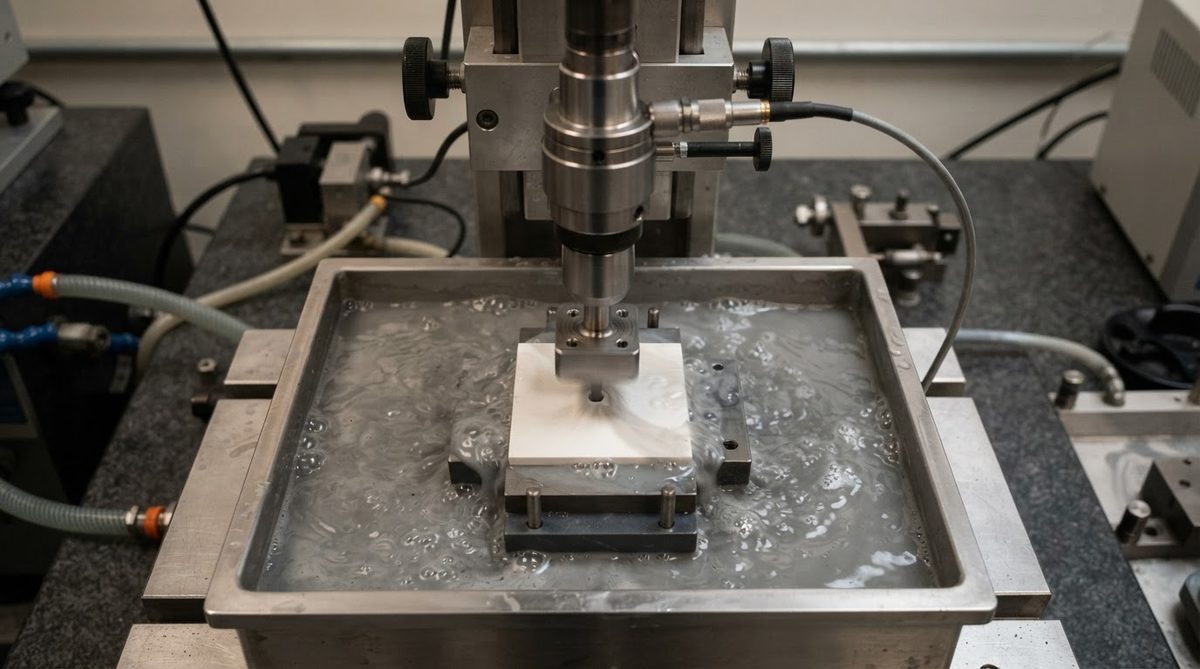
Ultrasonic machining (USM) uses a shaped tool vibrating at 20–40 kHz, with an abrasive slurry (typically boron carbide or silicon carbide grit) between the tool and the workpiece. The abrasive particles, not the tool, do the cutting. USM produces holes with minimal HAZ and no thermal damage, making it a viable option when learning how to drill ceramic substrate without introducing microcracking.
USM handles holes from about 0.15 mm up to several millimetres in diameter. Positional tolerance is ±15–25 µm, comparable to CO₂ laser but worse than UV laser. The main drawback is speed: a single 0.5 mm hole in 0.63 mm alumina takes 5–15 seconds depending on grit size and tool pressure. That makes USM uneconomical for boards with hundreds of vias but practical for prototypes or substrates with fewer than 20–30 holes.
Tool wear is significant. The shaped sonotrode tip erodes during machining, so hole diameter drifts over a production run. Operators must measure and replace tips at defined intervals. Budget 10–20% tool-wear cost on top of machine time for production volumes.
Method 3: Diamond-Tool Mechanical Drilling
Sintered or electroplated diamond core drills can bore holes ≥0.3 mm in fired alumina and AlN. The drill is a thin-walled tube coated with diamond grit; it grinds a ring and leaves a cylindrical core that breaks free. Coolant (water or water-soluble oil) is mandatory to flush debris and control temperature.
Diamond drilling gives the straightest walls of any post-fire method—taper under 2%—and handles substrates up to 2 mm thick without difficulty. Positional tolerance depends on the CNC spindle: ±10–20 µm is typical on a good machine. The lower limit on hole diameter is set by core-drill availability and fragility: below 0.3 mm, the diamond tube is too thin to survive. For engineers evaluating how to drill ceramic substrate for mounting holes, alignment pins, or slots larger than 1 mm, diamond tooling is the first choice. It is the worst choice for fine-pitch via arrays.
Method 4: Green-State Punching and CNC Machining
If you control the substrate from the tape-casting or pressing stage, the cheapest and fastest way to create holes is to punch or CNC-machine them before sintering. Unfired (“green”) alumina and AlN have the consistency of hard chalk. A simple steel punch or carbide micro-drill cuts through cleanly.
The catch is shrinkage. Alumina shrinks 15–20% linearly during sintering; AlN shrinks 17–22%. A hole punched at 0.50 mm in the green body may end up at 0.40–0.43 mm after firing. Positional accuracy also degrades: a ±10 µm punch placement becomes ±50–80 µm after sintering distortion. For HTCC and LTCC processes, this is managed through shrinkage-compensated tooling and statistical process control, but it sets a practical positional tolerance floor of ±50 µm for through-holes and ±25 µm for vias in production HTCC substrates.
Green-state machining is standard practice for high-volume ceramic packages (e.g., HTCC multilayer modules). If you are buying pre-fired blank substrates and need holes added, you are limited to the three post-fire methods above.
Enter your substrate material, thickness, and target hole diameter below to see which drilling method fits your requirements and estimate the temperature impact on the surrounding substrate.
Worked Example: Choosing a Method for 100 Vias in 0.38 mm Alumina
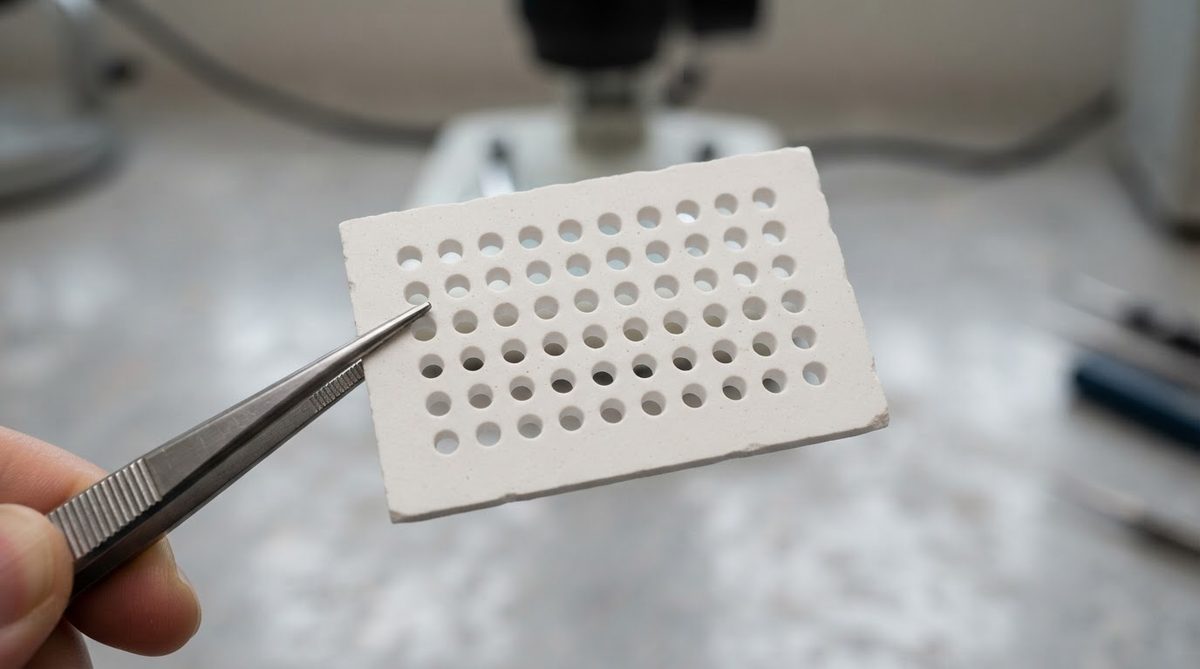
Suppose you need 100 through-vias of 0.20 mm diameter in a 25 × 25 mm, 0.38 mm thick, 96% alumina substrate, with positional tolerance ±20 µm. Here is how the methods compare:
- UV laser: 0.20 mm is within range (min ~50–80 µm). 100 holes at ~3 holes/sec = ~33 seconds of laser time. Positional accuracy ±10–15 µm meets the spec. Taper ~5%. This is the clear winner.
- CO₂ laser: 0.20 mm is at the edge of capability (min ~100–150 µm). Positional accuracy ±20–25 µm is marginal. Not recommended.
- Ultrasonic: 0.20 mm is achievable but each hole takes ~8–12 seconds. Total machining time: 15–20 minutes per substrate. Tolerance ±15–25 µm is marginal. Cost-prohibitive at volume.
- Diamond drill: 0.20 mm is below the practical minimum of 0.30 mm. Not feasible.
For this job, UV laser drilling is the only method that meets all three requirements (size, tolerance, throughput) simultaneously.
Comparison Table: All Four Methods
| Parameter | UV Laser | Ultrasonic | Diamond Drill | Green-State Punch |
|---|---|---|---|---|
| Min hole diameter (µm) | 50–80 | 150 | 300 | 100 (post-sinter) |
| Max substrate thickness (mm) | 0.63 | 2.0 | 2.0+ | N/A (pre-fire) |
| Positional tolerance (µm) | ±10–15 | ±15–25 | ±10–20 | ±25–80 (post-sinter) |
| Wall taper | 3–8% | <2% | <2% | <1% |
| Heat-affected zone | Yes (5–50 µm) | None | Minimal | None |
| Speed (holes/sec, 0.3 mm hole) | 2–10 | 0.07–0.2 | 0.1–0.5 | 5–50 |
| Best for | Fine vias, high count | Prototypes, no HAZ | Large holes, slots | High volume, HTCC/LTCC |
Typical values across commercial equipment and processes. Confirm against your vendor’s process data.
When Not to Drill Ceramic at All
If your design needs hundreds of vias at ≤100 µm pitch, fired ceramic substrates are the wrong starting point. Consider LTCC, where vias are punched in the green tape before lamination and co-firing—positional accuracy is better, and per-via cost is a fraction of post-fire laser drilling. If thermal performance is not critical and your via count is high, an FR-4 or metal-core PCB with standard mechanical drilling will be orders of magnitude cheaper. Understanding how to drill ceramic substrate is valuable, but the process makes sense only for substrates that must survive high temperatures, provide low dielectric loss, or match the CTE of semiconductor die. If none of those apply, you are paying a premium for no benefit.
Frequently Asked Questions
Can I drill alumina with a Dremel or hand-held rotary tool?
Only with a diamond-coated burr, and only for holes above ~1 mm. Hand-held tools lack the positional control and feed-rate consistency needed for substrate-grade work. Expect chipping on the exit side and poor dimensional accuracy. This approach is acceptable for rough prototyping or trimming edges, not for via creation.
Does laser drilling weaken the substrate?
Yes, slightly. The heat-affected zone around each hole contains microcracks that reduce local flexural strength by 10–20%, per studies on UV-laser-processed 96% alumina (Klotz et al., Journal of the European Ceramic Society, 2012). For most circuit applications this is not a structural concern, but for substrates under mechanical load, keep holes away from high-stress regions.
What is the smallest via I can get metallised after drilling?
Reliable via metallisation (screen-printed paste or sputtered/plated copper) is practical down to about 100 µm diameter in 0.38 mm substrates. Below 100 µm, paste does not fill reliably, and plating uniformity suffers. If you need sub-100 µm vias, discuss thin-film metallisation with your substrate vendor.
Is drilling AlN different from drilling alumina?
AlN is softer (10–12 GPa vs. 14–16 GPa) and ablates faster under CO₂ laser, but it reacts with moisture to form aluminum hydroxide. All drilling coolants and cleaning steps must use anhydrous or low-moisture fluids. Laser drilling in ambient air is fine because the process is dry, which is one reason laser is the default method for AlN vias.
How much does laser drilling add to substrate cost?
For a 25 × 25 mm alumina substrate with 50–200 vias, laser drilling typically adds 15–40% to the bare substrate price, depending on hole count and diameter. Green-state punching in an HTCC process adds less than 5% because the tooling cost is amortised across the batch.
Next Step
If you need substrates with pre-drilled vias or are evaluating whether to drill post-fire, start by reviewing the ceramic PCB FAQ for process options. You can also browse alumina 96% substrate stock to check standard sizes before requesting custom drilling. For a quote on substrates with laser-drilled vias, submit your design files through the quote form.