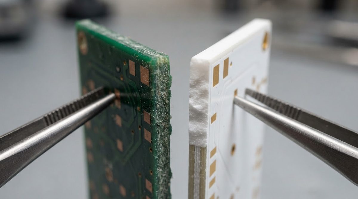
Why use ceramic PCB instead of FR-4 or metal-core? Because the substrate itself must conduct heat, survive high temperatures, or carry RF signals with minimal loss — jobs where organic and metal-core boards fall short. Ceramic substrates (Al₂O₃, AlN, Si₃N₄) offer thermal conductivities of 24–200 W/mK, continuous operating temperatures above 800 °C, and dielectric constants stable into the tens of GHz. The trade-off is higher cost and brittleness, which means ceramic is the right call only when a cheaper material genuinely cannot do the job.
Why Use Ceramic PCB? Seven Engineering Reasons
1. Thermal Conductivity That Replaces a Heat Sink
96% alumina conducts heat at 24–28 W/mK (per ASTM E1461, 20 °C). Aluminum nitride reaches 170–200 W/mK. Compare that to FR-4 at 0.3 W/mK. In a high-power LED or IGBT module, the ceramic substrate itself becomes the thermal path, often eliminating a separate heat spreader. For a quick comparison of aluminum nitride properties, AlN’s conductivity is roughly 6–8× that of alumina but costs 3–5× more per unit area.
2. Operating Temperature Far Above FR-4’s Limit
FR-4’s glass transition temperature (Tg) is typically 130–180 °C. Above that, the resin softens and delaminates. Alumina substrates remain dimensionally stable past 1 000 °C. This matters in downhole sensors, exhaust-gas probes, and furnace controls where ambient temperatures routinely exceed 300 °C. It is one of the clearest reasons why engineers use ceramic PCB technology for harsh-environment electronics.
3. CTE Matched to Silicon and GaAs
96% alumina has a CTE of approximately 7.1 ppm/°C (20–300 °C, per CoorsTek datasheet). Silicon sits at about 2.6 ppm/°C and GaAs at 5.7 ppm/°C. FR-4’s in-plane CTE is 14–17 ppm/°C. The closer CTE match reduces solder-joint fatigue during thermal cycling, which is critical for bare-die attach in power modules and MEMS packages.
4. Low and Stable Dielectric Loss at GHz Frequencies
96% alumina has a dissipation factor (tan δ) of roughly 0.0001–0.0003 at 1 MHz (per Kyocera A-493 datasheet). FR-4 sits around 0.02 at 1 GHz and climbs with frequency. For mmWave radar, 5G front-end modules, and precision RF filters, ceramic keeps insertion loss predictable across temperature and frequency.
5. Hermeticity
Fired ceramic is gas-tight. Combined with brazed metal seals, a ceramic circuit board package can achieve helium leak rates below 1 × 10⁻⁹ atm·cc/s per MIL-STD-883 Method 1014. Organic substrates cannot match this, which is why medical implants, aerospace sensor housings, and high-reliability laser packages default to ceramic.
6. Chemical Inertness
Alumina and AlN resist most acids, bases, and solvents at room temperature. In chemical-sensing applications or environments with aggressive cleaning agents, the substrate itself will not degrade over the product’s lifetime. This durability is another practical reason why use ceramic PCB designs persist in industrial and analytical instrumentation.
7. Dimensional Stability Over Decades
Ceramic does not absorb moisture, creep under load, or change dimensions with humidity. For precision optical mounts or long-life implantable devices, this stability eliminates a failure mode that organic boards carry.
Enter your substrate material, thickness, and target junction temperature below to see how ceramic compares to FR-4 and MCPCB under your actual thermal load.
Property Comparison: Ceramic vs. FR-4 vs. Metal-Core
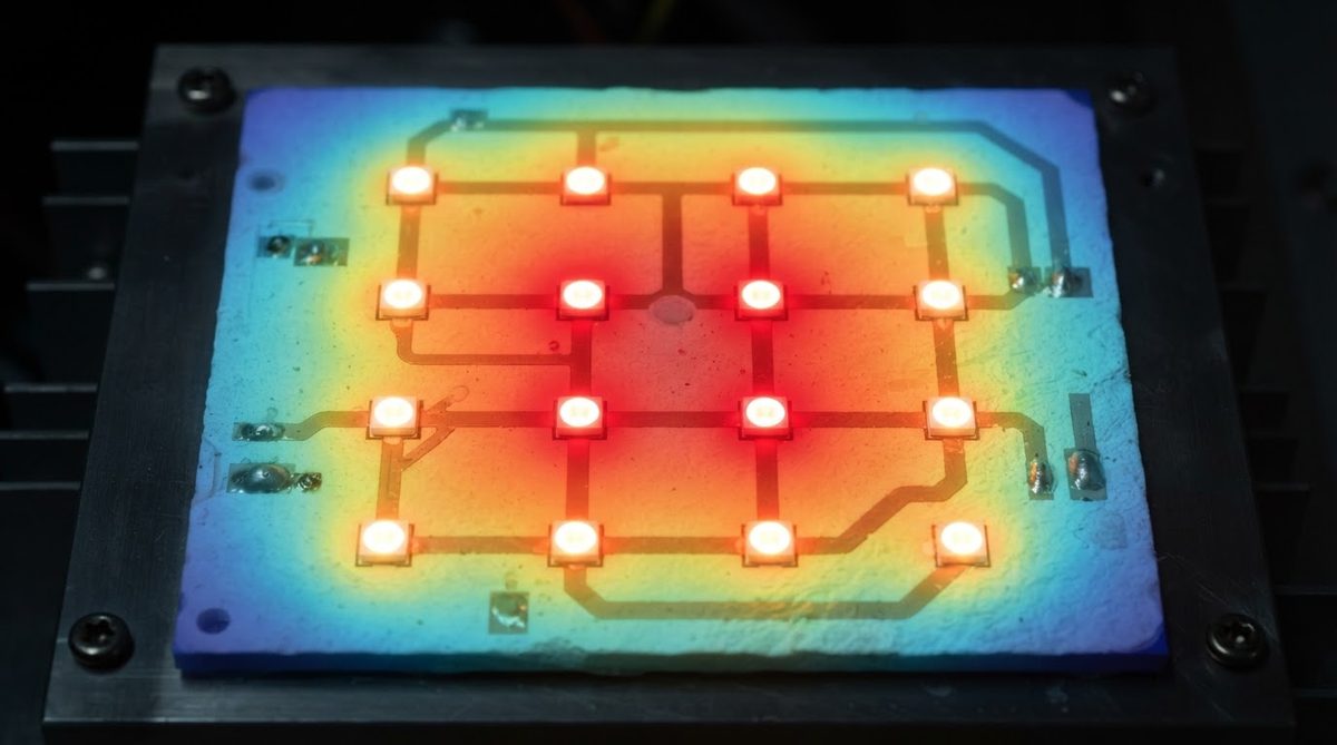
The table below puts hard numbers behind the reasons why use ceramic PCB substrates over alternatives. Every value includes a measurement condition and source so you can verify it against your own datasheets.
| Parameter | 96% Al₂O₃ | AlN | FR-4 | Aluminum MCPCB | Unit | Condition / Source |
|---|---|---|---|---|---|---|
| Thermal conductivity | 24–28 | 170–200 | 0.25–0.35 | 1–2 (dielectric layer) | W/mK | 20 °C; CoorsTek, Bergquist datasheets |
| Max continuous temp. | >1 000 | >1 000 | 130–180 (Tg) | 130–150 (dielectric Tg) | °C | Manufacturer ratings |
| CTE (20–300 °C) | 7.1 | 4.5 | 14–17 (in-plane) | 23 (aluminum) | ppm/°C | CoorsTek, IPC-4101 |
| Dielectric constant (1 MHz) | 9.4–9.8 | 8.5–9.0 | 4.2–4.8 | N/A (metal base) | — | Kyocera, Rogers datasheets |
| Dissipation factor (1 MHz) | 0.0001–0.0003 | 0.0003–0.001 | 0.015–0.025 | N/A | — | Kyocera A-493, IPC-4101 |
| Flexural strength | 300–380 | 300–350 | 415 (warp) | N/A | MPa | ASTM C1161, 3-pt bend |
| Relative cost (per cm²) | 5–10× | 15–30× | 1× | 2–4× | — | Industry estimates, small volume |
Typical values for commercially available material, for comparison only. Confirm against the datasheet for your specific grade.
When NOT to Use a Ceramic PCB
Ceramic is the wrong choice when cost, size, or mechanical shock dominates your constraints. Knowing why use ceramic PCB — and when not to — saves both time and budget. Specifically:
- Budget-driven consumer electronics. If the board runs below 100 °C and dissipates under 1 W/cm², FR-4 or a standard MCPCB will work at a fraction of the cost.
- Large boards. Ceramic substrates are typically limited to roughly 190 × 240 mm per panel. If your design is larger, you need FR-4 or a metal-core laminate.
- High mechanical shock or flex. Ceramic is brittle. A drop from desk height can crack an unsupported alumina board. For handheld devices subject to drops, flexible or rigid-flex organic PCBs are safer.
- Dense multilayer routing. HTCC and LTCC can build multilayer ceramic boards, but layer counts above 10–15 become expensive and slow. If your design needs 20+ layers of fine-pitch routing, organic HDI is the practical path.
For a deeper decision framework, see when a ceramic substrate is worth the investment.
Frequently Asked Questions
Is a ceramic PCB always better than a metal-core PCB for thermal management?
No. An aluminum MCPCB is cheaper and easier to machine into large panels. Ceramic wins when you also need electrical isolation at high voltage, CTE matching to semiconductors, or operation above 150 °C. If pure heat spreading at low cost is the goal, MCPCB is usually sufficient.
Can I get a ceramic PCB in small quantities for prototyping?
Yes. Many fabricators, including AluminaPCB, accept single-piece ceramic PCB orders. Expect higher per-unit cost at low volumes, but prototyping is routine.
Does ceramic PCB thickness affect performance?
Thinner substrates lower thermal resistance (Rth = thickness / (k × area)) but are more fragile. A 0.25 mm alumina board has half the Rth of a 0.5 mm board of the same area, but requires careful handling. The right thickness balances thermal performance against mechanical reliability in your assembly process.
What soldering methods work on ceramic substrates?
Standard reflow, wave, and hand soldering all work on metallized ceramic. The key difference is paste selection: active brazing pastes or high-temperature solders may be needed depending on the metallization. Eutectic SnAg and SAC305 are common for surface-mount assembly on DPC and thick-film metallized boards.
Are ceramic PCBs RoHS-compliant?
The ceramic substrate itself contains no restricted substances under RoHS. Compliance depends on the metallization, solder, and surface finish chosen. Standard lead-free processes (ENIG, ENEPIG, SAC305 solder) keep the full assembly RoHS-compliant.
Next Step
If your project involves high power density, temperatures above 150 °C, or RF frequencies above a few GHz, ceramic is likely the right substrate. Start by identifying the substrate material — our guide to 96% alumina covers the most common option. When you are ready to get pricing, request a quote through our online form.