When engineers compare alumina 96% Al2O3 vs FR4, the headline difference is thermal: 96% alumina conducts heat roughly 18–22× better than FR-4 (24–28 W/m·K versus 0.3–0.4 W/m·K per ASTM E1461), withstands continuous service above 800 °C instead of FR-4’s 130 °C ceiling, and maintains a stable dielectric constant through the GHz range. It also costs 8–15× more per unit area and breaks if you flex it. The choice comes down to whether your thermal, frequency, or reliability requirements exceed what organic laminate can handle.
Key Takeaways
- 96% alumina thermal conductivity is 24–28 W/m·K at 20 °C — roughly 70× the through-plane value of FR-4 (0.3–0.4 W/m·K), making it the default ceramic for power dissipation above ~2 W/cm².
- FR-4 glass transition temperature (Tg) is 130–180 °C depending on resin system; 96% alumina operates continuously above 800 °C with no decomposition.
- Dielectric constant of 96% alumina is 9.4–9.8 at 1 MHz (per Kyocera A-493 datasheet), while FR-4 is 4.2–4.7 at 1 MHz — both stable, but FR-4 drifts significantly above 1 GHz.
- FR-4 wins on cost, machinability, and panel size. For boards larger than ~150 mm × 150 mm with moderate thermals, FR-4 is almost always the right call.
- CTE of 96% alumina is 6.5–7.2 ppm/°C, close to silicon (2.6 ppm/°C) and GaN-on-SiC (4.2 ppm/°C), reducing solder-joint fatigue in die-attach applications.
Alumina 96% Al2O3 vs FR4: Property-by-Property Comparison
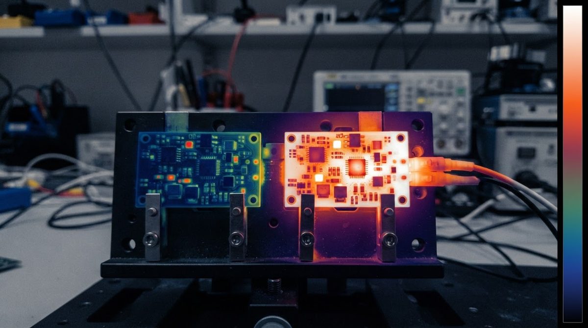
| Parameter | 96% Al₂O₃ | FR-4 (Tg 170) | Unit | Condition | Source |
|---|---|---|---|---|---|
| Thermal conductivity | 24–28 | 0.3–0.4 (through-plane) | W/m·K | 20 °C, ASTM E1461 | CoorsTek ADS-96R datasheet; IPC-4101E for FR-4 |
| Max continuous temperature | >800 (no organics) | 130–180 (Tg-limited) | °C | Long-term service | Kyocera A-493; IPC-4101E |
| Dielectric constant (εr) | 9.4–9.8 | 4.2–4.7 | — | 1 MHz, 25 °C | Kyocera A-493; Isola 370HR datasheet |
| Dissipation factor (tan δ) | 0.0001–0.0004 | 0.017–0.025 | — | 1 MHz, 25 °C | Same sources |
| CTE | 6.5–7.2 | 14–17 (x/y); 50–70 (z above Tg) | ppm/°C | 20–300 °C | CoorsTek ADS-96R; IPC-4101E |
| Flexural strength | 350–380 | 415–500 | MPa | ASTM C1161 (alumina); IPC-TM-650 (FR-4) | CoorsTek; Isola |
| Volume resistivity | >10¹⁴ | ~10⁸–10¹⁰ | Ω·cm | 25 °C | CoorsTek; Isola |
| Moisture absorption | 0 | 0.10–0.15 | % | 24 h immersion | Kyocera; IPC-4101E |
| Typical substrate cost (100 mm × 100 mm) | $8–$25 | $0.50–$2.00 | USD | Qty 100, bare substrate | Industry estimates |
Typical values for commercially available material, for comparison only. Confirm against the datasheet for your specific grade.
Thermal Performance: Alumina 96% Al2O3 vs FR4 Worked Example
Suppose you need to conduct 5 W through a 1.0 mm thick, 10 mm × 10 mm substrate to a heat sink. The one-dimensional thermal resistance through the substrate is:
Rth = t / (k × A)
For 96% alumina (k = 25 W/m·K):
Rth = 0.001 m / (25 × 0.0001 m²) = 0.40 °C/W
ΔT = 5 W × 0.40 °C/W = 2.0 °C
For FR-4 (k = 0.35 W/m·K through-plane):
Rth = 0.001 m / (0.35 × 0.0001 m²) = 28.6 °C/W
ΔT = 5 W × 28.6 °C/W = 143 °C
That 141 °C difference is the entire argument for ceramic in most power applications. At 5 W through a 10 × 10 mm footprint, FR-4 simply cannot keep the junction temperature within safe limits. Even thermal vias in FR-4 only bring effective through-plane conductivity to about 1–3 W/m·K — still an order of magnitude below alumina.
Enter your own substrate area, thickness, and dissipated power below to estimate junction temperature rise for both materials.
If your dissipation is under 0.5 W over the same area, the FR-4 rise is about 14 °C — often acceptable. That is the crossover zone where the alumina 96% Al2O3 vs FR4 decision gets interesting. For anything above roughly 2 W/cm², alumina is the default substrate unless a metal-core PCB fits the electrical requirements. For a detailed cost comparison between ceramic and metal-core PCBs, see our side-by-side analysis.
Where Alumina Wins Over FR-4
High-Temperature Environments
FR-4’s resin system begins to soften at its glass transition temperature (130–180 °C). Above Tg, z-axis CTE spikes to 50–70 ppm/°C, barrel cracks propagate through vias, and delamination follows. Alumina has no organic binder to decompose. Downhole sensors, exhaust-gas probes, and furnace controls routinely use 96% alumina substrates at 400–600 °C for years. If your operating environment exceeds 150 °C ambient, FR-4 is off the table regardless of thermal conductivity.
Power Density Above 2 W/cm²
LED arrays, SiC gate drivers, and RF power amplifiers concentrate heat in small footprints. As the worked example shows, alumina keeps ΔT manageable where FR-4 cannot. Processes like DBC and DPC metallization bond copper directly to the ceramic, eliminating the adhesive layer that adds thermal resistance in traditional laminates.
CTE-Matched Die Attach
Bare-die bonding of silicon (CTE 2.6 ppm/°C) or GaN-on-SiC (CTE ~4.2 ppm/°C) onto FR-4 (CTE 14–17 ppm/°C in-plane) creates large shear stress at the solder joint during thermal cycling. Alumina’s 6.5–7.2 ppm/°C is a much closer match. Over 1,000 thermal cycles (–40 to +125 °C per JEDEC JESD22-A104), the solder-joint fatigue life on alumina can be 5–10× longer than on FR-4, depending on joint geometry. This CTE advantage is one of the clearest wins in the alumina 96% Al2O3 vs FR4 comparison for power-semiconductor packaging.
RF and Microwave Stability
FR-4’s dissipation factor rises sharply above 1 GHz, reaching 0.02–0.03 at 10 GHz. Signal loss scales directly with tan δ. Alumina’s tan δ stays below 0.0004 through 10 GHz. For filters, couplers, and antenna feeds above 2 GHz, alumina or higher-purity grades provide predictable impedance. If your frequency pushes past 20 GHz, you may want to compare 96% alumina against 99.6% alumina, which offers even lower loss.
Where FR-4 Still Wins
Cost and Panel Size
FR-4 panels run up to 610 × 457 mm (24 × 18 in) in standard production. Alumina substrates rarely exceed 150 × 150 mm. The substrate cost difference is 8–15× per unit area, and FR-4 tooling is amortized across millions of boards worldwide. For consumer electronics, IoT nodes, and anything where thermal load per component is below ~1 W, FR-4’s economics are unbeatable.
Mechanical Flexibility
Alumina is a brittle ceramic. A 0.635 mm thick alumina board will fracture under a bending moment that barely stresses FR-4. Drop-test survival, board-level flex during connector insertion, and snap-apart panelization all favor FR-4. If your product must survive casual handling without a rigid enclosure, FR-4 or a flex-rigid stack is the safer choice.
Multilayer Complexity
Standard FR-4 fabrication supports 20+ layers with buried/blind vias at commodity pricing. Ceramic multilayer processes (HTCC, LTCC) exist but are far more expensive and limited in layer count. If your design needs six or more signal layers, FR-4 or a hybrid approach — ceramic substrate for the power stage, FR-4 for the logic — is more practical.
When NOT to Use 96% Alumina
Choose FR-4 or another substrate when:
- Ambient temperature stays below 130 °C and power density is under 1 W/cm².
- Board area exceeds 150 × 150 mm, or you need more than four routing layers.
- The product must survive repeated mechanical shock or flex without a protective housing.
- Unit cost targets are below $2 per board — ceramic cannot compete at that price point.
- Operating frequency is below 1 GHz and impedance tolerance of ±10% is acceptable.
For applications where FR-4 falls short but alumina’s cost is hard to justify, metal-core PCBs as an alternative offer a middle ground at 1–3 W/m·K through-plane conductivity. If you need even higher thermal conductivity than 96% alumina, aluminum nitride compared to FR-4 covers the next tier up at 170–200 W/m·K.
Decision Checklist
Run through these five questions for your board. If you answer “yes” to any of them, the alumina 96% Al2O3 vs FR4 trade-off tilts firmly toward ceramic:
- Does any component dissipate more than 2 W through a footprint smaller than 1 cm²?
- Will the board see sustained ambient temperatures above 150 °C?
- Are you bonding bare die with CTE below 7 ppm/°C directly to the substrate?
- Does the RF path operate above 2 GHz with insertion-loss budgets under 0.5 dB?
- Must the board survive 1,000+ thermal cycles between –40 °C and +125 °C without solder-joint failure?
If all five answers are “no,” FR-4 is almost certainly the right substrate. For a broader look at whether ceramic or FR-4 suits your project across other ceramic types, we cover that separately.
Frequently Asked Questions
Can I reflow-solder components onto 96% alumina the same way as FR-4?
Yes. Standard SAC305 reflow profiles (peak 245 °C) work on alumina substrates with no risk to the ceramic. The main difference is that alumina’s lower CTE means less board-level warpage during reflow, which actually improves BGA coplanarity. Use the same solder paste and stencil thickness you would for FR-4.
Does 96% alumina work for impedance-controlled traces?
It does, but the higher εr (9.4–9.8 vs 4.2–4.7 for FR-4) means traces are narrower for the same impedance. A 50 Ω microstrip on 0.635 mm alumina is roughly 0.55 mm wide, versus ~1.1 mm on 0.8 mm FR-4. Tighter trace widths demand finer lithography — DPC or thin-film processes handle this well.
How much does a 96% alumina board cost compared to FR-4?
Expect 8–15× the bare-substrate cost per unit area at prototype quantities. A 50 × 50 mm single-layer alumina DPC board might run $5–$12 each at qty 100, versus $0.30–$0.80 for FR-4. Total cost of ownership can shift the math if ceramic eliminates a heat sink, fan, or thermal interface material. See the full ceramic versus FR-4 cost breakdown for details.
Is 96% alumina safe to handle and machine?
96% alumina is chemically inert and non-toxic. It requires no special handling beyond normal ESD precautions. This is in contrast to beryllium oxide (BeO), which poses serious inhalation hazards. Laser scribing and diamond sawing are the standard methods for singulation; no hazardous dust is generated with proper extraction.
What surface finishes can I get on alumina?
Common finishes include ENIG, ENEPIG, OSP, and immersion silver — the same options available for FR-4. Thick-film gold (Au over Ni) is also widely used on ceramic for wire-bond pads. The choice depends on your assembly method, not the substrate material.
Next Step
If the alumina 96% Al2O3 vs FR4 comparison points your project toward ceramic, upload your design files for a quote. Our engineers can review your stackup and confirm whether 96% alumina, a higher-purity grade, or a different ceramic type fits your specific thermal and electrical targets.