The alumina 96% Al2O3 dielectric constant (relative permittivity, εr) is 9.0–9.5 at 1 MHz and 20 °C, per Kyocera and CoorsTek datasheets. This value is roughly two to three times higher than FR-4 (εr ≈ 4.2–4.5), which directly affects trace geometry, impedance, and signal propagation velocity on ceramic PCBs. Understanding exactly where this number comes from, how it shifts with frequency and temperature, and what it means for your stackup is essential before committing to an alumina substrate.
Key Takeaways
- The alumina 96% Al2O3 dielectric constant is 9.0–9.5 at 1 MHz (20 °C), per Kyocera and CoorsTek datasheets.
- Loss tangent (tan δ) is typically 0.0001–0.0004 at 1 MHz, making alumina far lower-loss than FR-4 (tan δ ≈ 0.02).
- εr decreases slightly with increasing frequency: expect roughly 9.3 at 1 GHz and 9.1–9.2 at 10 GHz for typical commercial 96% grades.
- Higher εr means narrower traces for the same impedance target—a 50 Ω microstrip on 0.635 mm alumina is about 0.59 mm wide versus 1.1 mm on FR-4.
- The glassy phase content (the remaining 4% of non-Al2O3 material) is the main variable that shifts εr between suppliers.
What Determines the Alumina 96% Al2O3 Dielectric Constant?
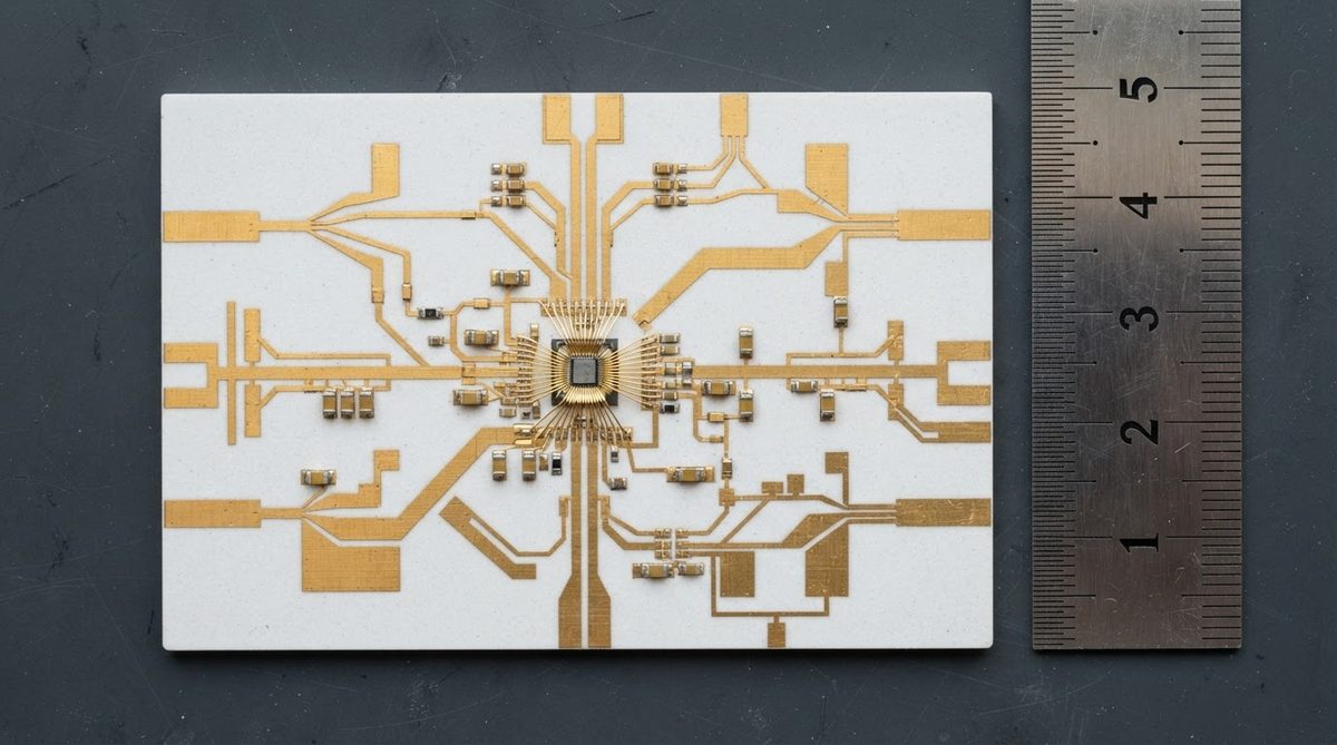
Pure single-crystal alumina (sapphire) has an εr of about 9.4 along the c-axis and 11.5 along the a-axis at 1 MHz, per the CRC Handbook of Chemistry and Physics. Polycrystalline 96% alumina is isotropic and averages lower because 4% of the body is a silicate glass phase used as a sintering aid. This glass phase has an εr of roughly 5–7, pulling the composite value down into the 9.0–9.5 range.
Different manufacturers use different glass compositions (SiO2–MgO–CaO blends vary), which is why you see a range rather than a single number. A full 96% alumina properties datasheet will list the specific εr for that grade. Always confirm the value against your supplier’s data rather than using a handbook number.
Dielectric Properties Table: 96% Al2O3
| Parameter | Value | Unit | Condition | Source |
|---|---|---|---|---|
| Dielectric constant (εr) | 9.0–9.5 | — | 1 MHz, 20 °C | Kyocera A-493 datasheet; CoorsTek AD-96 |
| Dielectric constant (εr) | 9.1–9.4 | — | 1 GHz, 20 °C | Kyocera A-493 datasheet |
| Dielectric constant (εr) | 9.0–9.2 | — | 10 GHz, 20 °C | CoorsTek AD-96 |
| Loss tangent (tan δ) | 0.0001–0.0004 | — | 1 MHz, 20 °C | Kyocera A-493; Maruwa HA-96 |
| Loss tangent (tan δ) | 0.0002–0.0006 | — | 10 GHz, 20 °C | CoorsTek AD-96 |
| Dielectric strength | 10–15 | kV/mm | AC, 60 Hz, 1 mm thick | CoorsTek AD-96 |
| Volume resistivity | >1014 | Ω·cm | 20 °C | Kyocera A-493 |
Typical values for commercially available material, for comparison only. Confirm against the datasheet for your specific grade.
How the Alumina 96% Al2O3 Dielectric Constant Changes with Frequency and Temperature
Alumina’s εr is remarkably stable compared to organic laminates. From 1 MHz to 10 GHz, the drop is less than 4%. FR-4, by contrast, can shift 5–10% over the same range. This stability is one of the primary reasons RF designers choose alumina for filters, couplers, and antenna feed networks.
Temperature dependence is also mild. The temperature coefficient of εr for 96% alumina is approximately +100 to +150 ppm/°C (per CeramTec data). Over a 100 °C swing from 25 °C to 125 °C, εr increases by roughly 0.09–0.14—a shift of about 1–1.5%. For most power-electronic applications this is negligible. For precision RF filters with tight bandwidth specs, it is worth including in your thermal analysis.
Enter your operating frequency and temperature below to see how the alumina 96% Al2O3 dielectric constant shifts for your specific conditions and estimate the resulting effective permittivity.
How εr Affects Impedance: A Worked Example
A common design task is sizing a 50 Ω microstrip on a 96% alumina substrate. Using the Hammerstad-Jensen closed-form approximation for microstrip impedance:
Given: εr = 9.3, substrate thickness h = 0.635 mm (25 mil), copper thickness t = 0.035 mm (1 oz equivalent), target Z₀ = 50 Ω.
Result: The required trace width w ≈ 0.59 mm (23.2 mil). On FR-4 (εr = 4.3) with the same 0.635 mm thickness, 50 Ω needs w ≈ 1.17 mm (46.1 mil)—almost exactly double. The higher εr of alumina lets you fit more traces in less space, which is a real advantage in dense hybrid circuits.
Signal velocity: The effective εr for this microstrip is about 6.3, giving a propagation velocity of roughly 1.20 × 10⁸ m/s (about 40% of free-space speed). On FR-4 the effective εr is around 3.3, so signals travel faster. In timing-critical digital designs on alumina, account for the slower propagation in your length-matching rules.
96% Alumina vs. Other Ceramic Substrates: Dielectric Comparison
| Material | εr (1 MHz) | tan δ (1 MHz) | Thermal Conductivity (W/m·K) | Relative Cost |
|---|---|---|---|---|
| 96% Al2O3 | 9.0–9.5 | 0.0001–0.0004 | 24–28 | 1× |
| 99.6% Al2O3 | 9.7–10.0 | 0.0001–0.0002 | 28–35 | 1.5–2× |
| AlN | 8.5–9.0 | 0.0003–0.001 | 170–200 | 3–5× |
| LTCC (various) | 5.0–9.0 | 0.001–0.003 | 2–4 | 2–4× |
| FR-4 | 4.2–4.5 | 0.018–0.025 | 0.3–0.4 | 0.1× |
Typical values for commercially available material, for comparison only. Confirm against the datasheet for your specific grade.
If your design needs a lower εr for wider traces or reduced parasitic capacitance, aluminum nitride dielectric properties offer a slightly lower εr (8.5–9.0) with dramatically better thermal conductivity. For higher-purity alumina with tighter εr tolerance, see 99.6% alumina material properties. A broader comparison of all ceramic substrate dielectric properties is available on the overview page.
Design Considerations When Using an εr of 9.0–9.5
Trace Width and Spacing
The higher alumina 96% Al2O3 dielectric constant concentrates the electric field more tightly under the trace. This means coupling between adjacent traces is stronger for a given edge-to-edge gap. Increase your spacing rules by roughly 30–50% compared to FR-4 rules at the same frequency to maintain equivalent crosstalk performance.
Via and Pad Parasitics
Via-to-ground capacitance scales with εr. A through-via in 0.635 mm alumina with a 0.3 mm drill and 0.6 mm pad has about 0.08 pF of parasitic capacitance—small, but roughly double what the same geometry produces in FR-4. At frequencies above 5 GHz, account for this in your S-parameter models.
Thick-Film vs. Thin-Film Metallization
Thick-film conductors (screen-printed Ag, Au, or AgPd) have rough edges that increase effective line width by 25–50 µm. This shifts impedance downward. Thin-film (sputtered and etched) metallization holds tighter trace tolerances (±5–10 µm), giving more predictable impedance. Choose metallization method based on your frequency and impedance tolerance budget.
When Not to Use 96% Alumina for Its Dielectric Properties
Low-εr applications. If your circuit needs εr below 5 for wide traces or reduced coupling (e.g., broadband antenna arrays), alumina is the wrong substrate. Consider PTFE-ceramic composites (Rogers RO4003C, εr ≈ 3.38) or quartz (εr ≈ 3.8).
Cost-driven consumer products. If dielectric loss is not a concern and your operating temperature stays below 130 °C, FR-4 or high-Tg FR-4 will cost 5–10× less per panel. Alumina’s low loss tangent is wasted on a 100 MHz digital bus.
Large-area boards. Standard alumina substrates max out around 150 mm × 150 mm. If your design exceeds that, you need panel tiling or a different substrate entirely.
FAQ
Does the dielectric constant of 96% alumina change after metallization firing?
No. Thick-film firing (850 °C peak for Ag, 950 °C for Au) does not measurably change the bulk εr of an already-sintered alumina substrate. The ceramic was originally sintered above 1,500 °C, so refiring at lower temperatures has negligible effect on its crystal structure or glassy phase.
Can I use 96% alumina at millimeter-wave frequencies (30 GHz+)?
Yes, but with caution. The εr remains around 9.0–9.2 at 30 GHz, and loss tangent rises to roughly 0.001. Surface roughness of the substrate and metallization becomes the dominant loss mechanism above 20 GHz. Polished substrates with thin-film metallization are preferred. See polished 96% alumina substrates for surface-finish options.
How do I measure εr of an alumina substrate I already have?
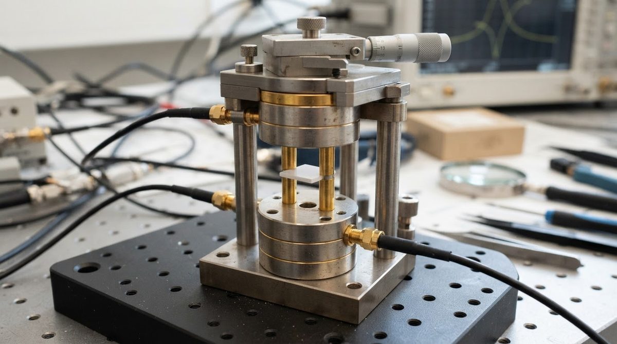
The most accessible method is the split-post dielectric resonator (SPDR) technique per IEC 61189-2-721. It gives εr and tan δ at a single frequency (typically 10 GHz) with ±0.5% accuracy. A resonant cavity method per ASTM D2520 works well for lower frequencies. Both require a flat, unmetallized coupon.
Is the alumina 96% Al2O3 dielectric constant isotropic?
Yes. Polycrystalline alumina is randomly oriented, so εr is the same in all directions. This is an advantage over sapphire (single-crystal Al2O3), which is anisotropic and requires careful orientation of the crystal axis relative to the circuit.
What tolerance should I expect on εr from lot to lot?
Most ceramic suppliers specify εr within ±0.2 of the nominal value for 96% alumina. If your impedance budget requires tighter control, request incoming inspection data or consider 99.6% alumina, which has less glassy phase and therefore less lot-to-lot variation in the alumina 96% Al2O3 dielectric constant.
Next Step
If you are designing a circuit on 96% alumina and need substrates with a confirmed εr value, request a quote with your thickness, metallization, and frequency requirements. Datasheets with measured dielectric data for the specific grade are available on request.