What Is CTE? A Practical CTE Definition
The CTE definition used in electronics is straightforward: CTE (coefficient of thermal expansion) is the fractional change in length of a material per degree of temperature change, expressed in ppm/°C (parts per million per degree Celsius). A material with a CTE of 7 ppm/°C expands 7 µm for every metre of length for every 1 °C rise in temperature. Understanding this cte definition is essential when selecting substrates, because every material on a ceramic PCB assembly expands at a different rate.
CTE matters in electronics because every thermal cycle—power-on, power-off, ambient swings—forces joined materials to expand and contract at different rates. When a ceramic substrate, a copper trace layer, and a silicon die all have different CTEs, the resulting shear stress concentrates at solder joints and die-attach interfaces. Over hundreds or thousands of cycles, this mismatch drives fatigue cracks and eventual failure.
Why the CTE Definition Matters for Substrate Selection
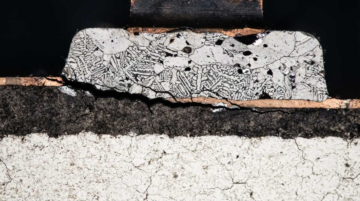
Applying the CTE definition to real materials reveals large differences. Copper expands roughly 2.5× more per degree than 96% alumina, and nearly 6× more than silicon. These gaps create mechanical stress every time a board heats up or cools down. Choosing a substrate with a CTE close to the die material reduces that stress and extends assembly life.
Key reasons engineers track CTE during design:
- Bare-die attach joints fail faster when the CTE mismatch between substrate and silicon exceeds 3–4 ppm/°C.
- Copper metallisation on ceramic creates a bimetallic-strip effect; thicker copper amplifies warpage.
- Thermal-cycle qualification tests (e.g., −40 °C to +150 °C per JEDEC JESD22-A104) expose CTE-driven fatigue within hundreds of cycles.
- Compliant attach materials (silver sinter, soft solders) can compensate for moderate mismatch but add cost and process complexity.
Typical CTE Values for Ceramic PCB Materials
| Material | CTE (ppm/°C) | Temp. Range | Source |
|---|---|---|---|
| Silicon (die) | 2.6–3.3 | 25–300 °C | JEDEC JEP148 |
| 96% Al₂O₃ | 6.5–7.2 | 25–300 °C | CoorsTek ADS-96R datasheet |
| AlN | 4.4–5.0 | 25–300 °C | Kyocera SH-30 datasheet |
| Si₃N₄ | 2.5–3.4 | 25–300 °C | CeramTec product data |
| Copper (trace) | 16.5–17.5 | 25–300 °C | ASTM E228 |
| FR-4 (x-y plane) | 14–18 | 25–260 °C | IPC-4101E |
Typical values for commercially available material, for comparison only. Confirm against the datasheet for your specific grade.
Notice that Si₃N₄ and AlN sit much closer to silicon’s CTE than copper or FR-4 does. This is one reason ceramic substrates are preferred for bare-die power modules: the closer CTE match reduces stress at the die-attach layer and extends thermal-cycle life.
Enter your substrate material, copper thickness, and operating temperature range to see the estimated thermal-expansion mismatch and stress factor for your assembly.
Why CTE Mismatch Causes Failures
In a DCB (direct copper bond) assembly, a 0.3 mm copper layer bonded to a 0.635 mm Al₂O₃ substrate creates a bimetallic strip effect. The copper wants to expand roughly 2.5× more than the alumina per degree. During sintering or reflow, residual stress locks in as the assembly cools. Each subsequent thermal cycle adds fatigue strain to the bond interface.
Design countermeasures include choosing substrates with a CTE closer to the die, using compliant solder alloys or silver-sintered attach layers, and dimpling copper patterns to relieve stress at corners. The CTE definition gives you the number; the design rules tell you what to do with it.
When CTE Mismatch Is Less Important
If your board carries only surface-mount passives and packaged ICs—not bare die—CTE mismatch between substrate and silicon is absorbed by the package itself. In that case, standard FR-4 or metal-core PCBs may be adequate, and the higher cost of a ceramic substrate is harder to justify on CTE grounds alone.
FAQ
Is CTE constant across all temperatures?
No. CTE varies with temperature. Most datasheets report an average value over a stated range (e.g., 25–300 °C). Above the glass-transition temperature of polymers, CTE can jump sharply—this is less of a concern with ceramics, which have no Tg.
What CTE mismatch is considered safe?
A common guideline is to keep the CTE difference between bonded layers below 3–4 ppm/°C for bare-die attach. Larger mismatches can work if the joint is compliant or the thermal cycle range is narrow.
Does CTE affect HTCC and LTCC differently?
Yes. HTCC alumina substrates have a CTE around 6.5–7.2 ppm/°C, while LTCC glass-ceramic systems typically range from 5.5–7.0 ppm/°C depending on composition. The co-fired conductor paste must also be CTE-compatible with the green tape.
How is CTE measured?
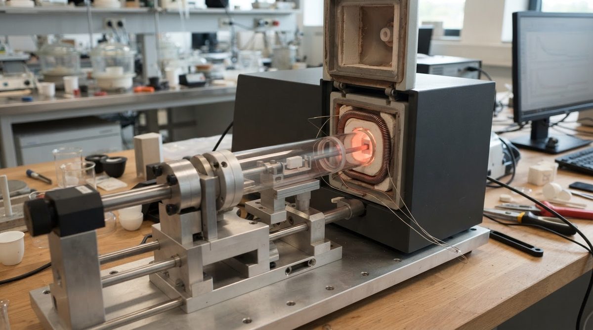
The standard method is dilatometry per ASTM E228. A sample is heated at a controlled rate while a probe measures length change. Thermomechanical analysis (TMA) per ASTM E831 is used for smaller samples and thin films. Both methods produce the data behind every CTE definition you see on a datasheet.