When evaluating a ceramic PCB vs metal core substrate, the core trade-off is performance against cost. Ceramic PCBs outperform metal-core PCBs (MCPCBs) in thermal conductivity, dielectric strength, CTE match to semiconductors, and high-frequency loss — but they cost 5–20× more per unit area and crack under mechanical shock. If your design is thermally limited, runs above 300 °C, or operates at RF frequencies, ceramic is the better substrate. If you need large panels, low cost, and adequate (not exceptional) heat spreading, MCPCB wins.
Key Takeaways
- AlN ceramic conducts 170–200 W/m·K; a typical MCPCB dielectric layer conducts only 1–4 W/m·K, creating a thermal bottleneck despite the aluminum base.
- Ceramic substrates operate continuously above 800 °C; MCPCB dielectric layers degrade above 130–150 °C.
- 96% Al₂O₃ has a CTE of ~7 ppm/°C, close to GaN (3.2 ppm/°C) and SiC (4 ppm/°C). Aluminum MCPCBs sit at ~23 ppm/°C — a large mismatch that stresses die-attach joints.
- MCPCBs are available in panels up to 600 × 500 mm at a fraction of ceramic cost, making them practical for general LED and power-supply designs.
- Ceramic is brittle. Any application with vibration, flex, or drop risk needs careful mechanical design or a different substrate.
Ceramic PCB vs Metal Core: How Thermal Performance Actually Compares
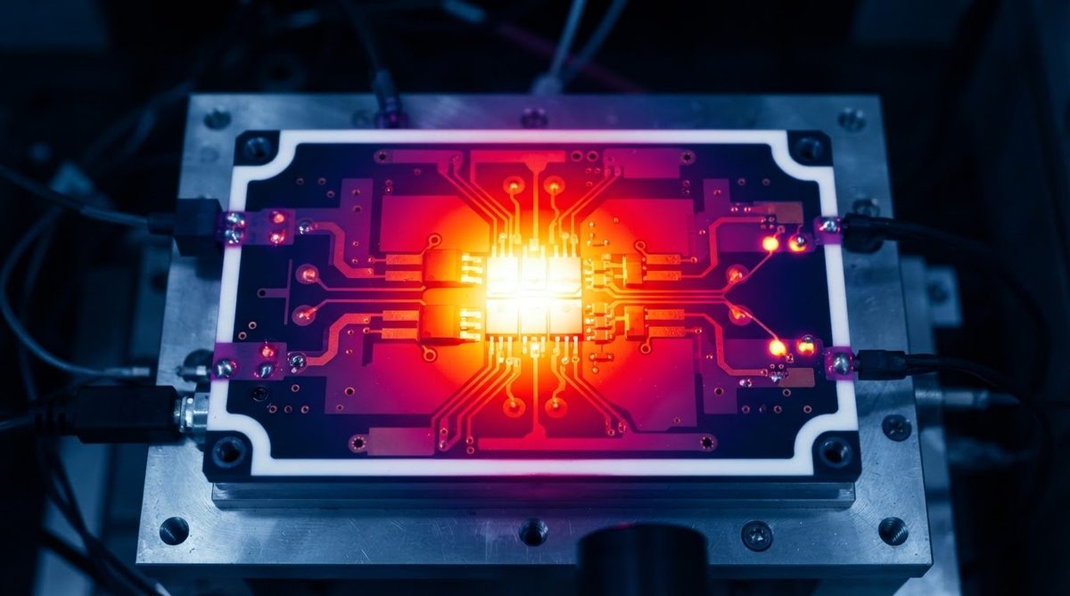
Engineers often assume an aluminum-base MCPCB conducts heat as well as the aluminum itself (150–200 W/m·K). It does not. The dielectric layer between the copper circuit and the aluminum base is the real thermal resistance. Standard epoxy-filled dielectrics measure 1–3 W/m·K; premium versions reach 4–8 W/m·K (per Bergquist/Henkel HT series datasheets). That 50–100 µm layer dominates the stack’s total thermal resistance.
A ceramic circuit board has no polymer dielectric. The substrate itself is the insulator. At 96% Al₂O₃ (24–28 W/m·K) or AlN (170–200 W/m·K), the bulk material conducts heat far more effectively than any MCPCB dielectric layer. This fundamental structural difference is why the ceramic PCB vs metal core debate matters most in high-power-density designs.
Worked Example: Thermal Resistance Through the Dielectric
Consider a 10 × 10 mm heat source dissipating 20 W. Compare the one-dimensional thermal resistance (Rth = t / (k × A)) through the insulating layer alone:
| Parameter | MCPCB (premium dielectric) | 96% Al₂O₃ (0.635 mm) | AlN (0.635 mm) |
|---|---|---|---|
| Thickness (mm) | 0.075 | 0.635 | 0.635 |
| k (W/m·K) | 4 | 26 | 180 |
| Area (m²) | 1 × 10⁻⁴ | 1 × 10⁻⁴ | 1 × 10⁻⁴ |
| Rth (°C/W) | 1.88 | 2.44 | 0.35 |
| ΔT at 20 W (°C) | 37.5 | 48.8 | 7.1 |
Typical values for commercially available material, for comparison only. Confirm against the datasheet for your specific grade.
The MCPCB’s thin dielectric keeps its Rth competitive with alumina despite far lower conductivity. But AlN is in a different league — ΔT drops to 7 °C. For high-power-density devices (SiC MOSFETs, UV LEDs, laser diodes), that difference determines whether you need active cooling.
Enter your substrate area, thickness, and dissipated power below to estimate junction temperature rise for your own design.
Electrical and High-Frequency Behavior
Ceramic substrates have dielectric constants and loss tangents that remain stable across temperature and frequency. 96% Al₂O₃ has a dielectric constant of ~9.6 and a loss tangent of 0.0001–0.0004 at 1 MHz (per CoorsTek ADS-96R datasheet). MCPCB dielectric layers, being filled polymers, show loss tangents of 0.02–0.03 — roughly 50–100× higher. Above a few hundred MHz, signal integrity on an MCPCB degrades noticeably. This is another area where the ceramic PCB vs metal core comparison tilts decisively toward ceramic for RF and mmWave circuits.
Dielectric strength also differs. Al₂O₃ withstands 10–15 kV/mm; AlN withstands 15–17 kV/mm. MCPCB dielectrics are rated at 3–6 kV/mm. For high-voltage isolation in power modules, ceramic provides a wider safety margin in a thinner cross-section.
CTE Match and Reliability Under Thermal Cycling
CTE mismatch between substrate and die is the primary driver of solder-joint fatigue in power electronics. The table below shows the gap:
| Material | CTE (ppm/°C, 20–300 °C) | Source |
|---|---|---|
| Si die | 2.6 | JEDEC JEP154 |
| SiC die | 4.0 | Wolfspeed app note AN019 |
| GaN-on-Si | 3.2–5.6 | Infineon AN2019-09 |
| 96% Al₂O₃ | 7.1 | CoorsTek ADS-96R |
| AlN | 4.5 | Kyocera SH-50 datasheet |
| Si₃N₄ (AMB substrate) | 2.7 | Kyocera SN-01 datasheet |
| Aluminum (6061) | 23.6 | ASM Alloy Digest |
| Copper | 17.0 | ASM Alloy Digest |
Typical values for commercially available material, for comparison only. Confirm against the datasheet for your specific grade.
An aluminum MCPCB has a CTE mismatch of ~20 ppm/°C against a SiC die. Under power cycling (-40 °C to +150 °C), that gap drives crack propagation in die-attach solder within a few thousand cycles. AlN at 4.5 ppm/°C brings the mismatch below 1 ppm/°C, extending solder-joint life by an order of magnitude in accelerated testing. For reliability-critical designs, the ceramic PCB vs metal core decision often comes down to this single parameter.
Cost and Panel Size
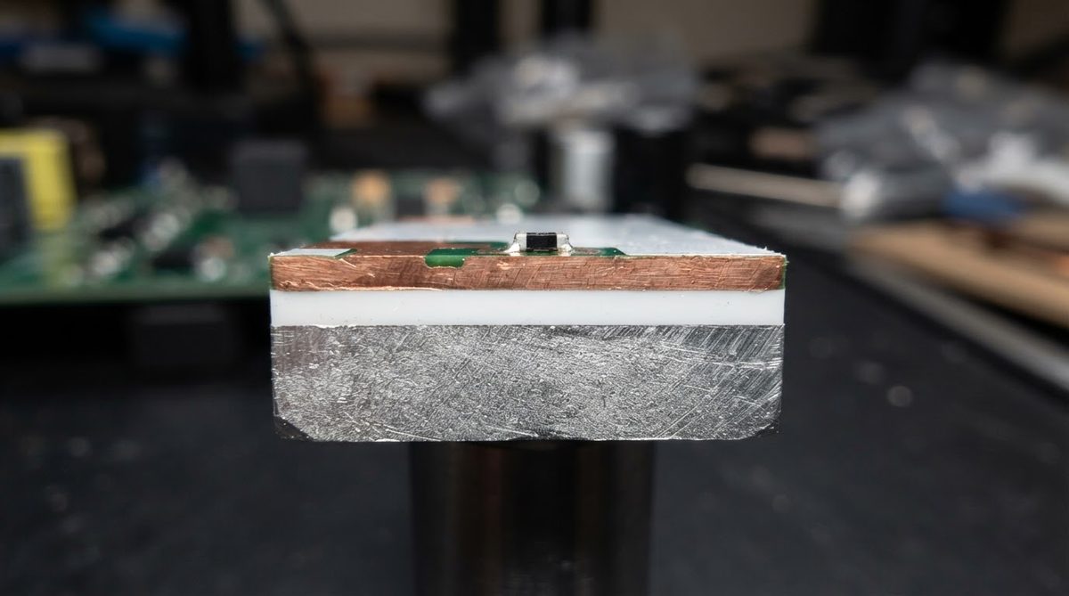
MCPCBs are manufactured on standard PCB lines using aluminum or copper base plates laminated with a filled-polymer dielectric. Panels can reach 600 × 500 mm. Tooling is inexpensive. Unit costs for a single-layer 1 oz Cu MCPCB run $0.02–$0.10 per cm² in volume.
Ceramic PCBs require sintering, laser drilling, and metallization processes (DPC, DBC, or thick-film). Substrate sizes rarely exceed 150 × 150 mm. Unit costs range from $0.30–$2.00 per cm² depending on material and metallization. The gap narrows for small substrates (< 25 × 25 mm) produced in volume, but ceramic never matches MCPCB on price per area. For a detailed breakdown, see the ceramic PCB cost guide.
When NOT to Use Ceramic
Choose MCPCB or standard FR-4 instead of ceramic when:
- Board area exceeds ~100 × 100 mm and thermal density is moderate (< 1 W/cm²). MCPCB handles this at a fraction of the cost.
- The product faces mechanical shock or vibration. Ceramic cracks. MCPCBs and FR-4 flex. For automotive underbody or handheld-device applications, ceramic needs a compliant mounting scheme or should be avoided.
- Budget is the primary constraint. If the thermal problem can be solved with a heatsink and a $0.50 MCPCB, spending $8 on a ceramic substrate adds no value.
- Rapid prototyping with fast turns. MCPCB lead times are 3–5 days from many shops. Ceramic prototypes typically take 2–4 weeks. Check available ceramic PCB thicknesses early to avoid surprises.
Decision Framework
Run through these four questions in order:
- Is junction temperature the limiting factor? If yes, and the MCPCB Rth calculation above does not meet your thermal budget, move to ceramic (AlN or DBC Al₂O₃).
- Does the design operate above 150 °C ambient or require > 5 kV isolation? Ceramic is likely necessary. MCPCB dielectrics degrade at sustained temperatures above 130–150 °C.
- Is the circuit RF (> 500 MHz)? Ceramic’s low loss tangent preserves signal integrity. MCPCB dielectric losses become significant.
- Is CTE mismatch causing field failures? Switching to AlN or Si₃N₄ from MCPCB can extend thermal-cycling life by 5–10×.
If all four answers are “no,” MCPCB is the right call. Save the budget for the heatsink and thermal interface material.
FAQ
Can I replace an MCPCB with a ceramic PCB without redesigning?
Usually not. Ceramic substrates are smaller, thinner, and require different drill and routing methods. Pad geometries, soldering profiles for ceramic boards, and mounting hardware all need review. Plan a layout respin.
Do MCPCBs work for double-sided circuits?
Standard MCPCBs are single-layer only because the metal base plate is not drillable for plated through-holes. Some manufacturers offer two-layer MCPCBs with thermal vias, but options are limited. Ceramic PCBs support double-sided metallization and vias as standard.
Which substrate lasts longer under thermal cycling?
Ceramic substrates with matched CTE (AlN, Si₃N₄) outlast MCPCBs by a wide margin in thermal-cycling tests. The polymer dielectric in MCPCBs delaminates and the large CTE mismatch fatigues solder joints. For applications requiring > 3,000 power cycles at ΔT > 100 °C, ceramic is the safer choice.
Is copper-base MCPCB a viable middle ground?
Copper-base MCPCBs improve thermal conductivity of the base plate (~390 W/m·K vs ~150 W/m·K for aluminum) but the dielectric layer remains the bottleneck. They cost 2–3× more than aluminum MCPCBs and still cannot match AlN ceramic on total Rth or CTE.
What is the maximum operating temperature of a ceramic PCB vs metal core?
Al₂O₃ and AlN substrates themselves are stable above 1,000 °C. The practical limit is set by the metallization and solder: thick-film gold conductors survive 850 °C+, while DBC copper is rated to ~400 °C continuous. MCPCBs are limited to 130–150 °C by their polymer dielectric. This temperature ceiling is often the deciding factor in the ceramic PCB vs metal core choice for harsh-environment electronics.