Introduction to PCB Visualizer
PCB Visualizer is a powerful tool that allows engineers, designers, and hobbyists to create, visualize, and analyze printed circuit board (PCB) designs. With its intuitive interface and comprehensive features, PCBVisualizer streamlines the PCB design process, making it easier and more efficient than ever before.
What is a PCB?
A printed circuit board (PCB) is a flat board made of insulating material, such as fiberglass or plastic, with conductive pathways printed or etched onto its surface. These pathways, known as traces, connect various electronic components, such as resistors, capacitors, and integrated circuits (ICs), to create a functional electronic circuit.
PCBs are essential in modern electronics, as they provide a compact, reliable, and cost-effective way to assemble and connect electronic components. They are used in a wide range of applications, from consumer electronics and computers to industrial equipment and aerospace systems.
The Importance of PCB Design
Designing a PCB is a critical step in the development of any electronic device. A well-designed PCB ensures that the device functions correctly, reliably, and efficiently. Poor PCB design, on the other hand, can lead to a host of problems, such as signal integrity issues, electromagnetic interference (EMI), and even complete device failure.
Some of the key factors to consider when designing a PCB include:
- Component placement and routing
- Signal integrity and impedance matching
- Power distribution and decoupling
- Thermal management
- Manufacturing considerations (e.g., design for manufacturability, design for assembly)
Traditionally, PCB design has been a time-consuming and complex process, requiring specialized knowledge and tools. However, with the advent of PCB design software like PCBVisualizer, the process has become much more accessible and efficient.
Features and Benefits of PCBVisualizer
Intuitive User Interface
One of the key features of PCBVisualizer is its intuitive and user-friendly interface. The software provides a clean, uncluttered workspace that allows users to focus on their designs without being overwhelmed by unnecessary options or settings.
The main window is divided into several panels, each serving a specific purpose:
- The design panel, where users can place and route components
- The layer panel, which allows users to manage the various layers of the PCB (e.g., top layer, bottom layer, power planes)
- The properties panel, where users can adjust the properties of selected objects (e.g., component values, trace widths)
- The 3D view panel, which provides a realistic, three-dimensional representation of the PCB
This well-organized layout makes it easy for users to navigate the software and find the tools they need quickly.
Comprehensive Component Library
Another key feature of PCBVisualizer is its comprehensive component library. The software includes a vast collection of pre-designed components, ranging from basic passive components (e.g., resistors, capacitors) to complex ICs and connectors.
The component library is organized into categories and subcategories, making it easy to find the components you need. Users can also create their own custom components or import components from external sources, such as manufacturer datasheets or third-party libraries.
Having access to a wide range of components is essential for efficient PCB design, as it allows users to quickly populate their designs without having to create each component from scratch.
Powerful Routing Tools
Routing is one of the most critical and time-consuming aspects of PCB design. It involves creating the conductive paths (traces) that connect the various components on the board. Proper routing is essential for ensuring signal integrity, minimizing crosstalk and EMI, and meeting manufacturing constraints.
PCBVisualizer offers a range of powerful routing tools that make this process faster and more efficient:
- Auto-routing: The software can automatically route traces between components based on user-defined constraints (e.g., trace width, spacing, layer assignments). This can save significant time and effort, especially for complex designs.
- Interactive routing: Users can manually route traces using a variety of tools, such as the single-line router, the multi-line router, and the differential pair router. These tools provide precise control over trace placement and allow users to fine-tune their designs as needed.
- Routing constraints: PCBVisualizer allows users to define various routing constraints, such as minimum trace widths, spacing requirements, and via sizes. These constraints help ensure that the design meets manufacturing and performance requirements.
With these powerful routing tools, PCBVisualizer makes it easy to create high-quality, reliable PCB designs quickly and efficiently.
Real-Time Design Rule Checking (DRC)
Design rule checking (DRC) is a critical step in the PCB design process. It involves verifying that the design meets various manufacturing and performance constraints, such as minimum trace widths, spacing requirements, and drill sizes.
Traditionally, DRC has been a separate step performed after the design is complete. However, PCBVisualizer offers real-time DRC, which means that the software continuously checks the design against the specified rules as the user works.
If a design rule violation is detected, PCBVisualizer immediately alerts the user and provides guidance on how to resolve the issue. This real-time feedback helps catch and correct errors early in the design process, reducing the risk of costly redesigns or manufacturing issues down the line.
Real-time DRC is a significant time-saver and helps ensure that the final design is error-free and ready for manufacturing.
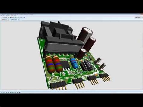
3D Visualization
PCBVisualizer also offers powerful 3D visualization capabilities that allow users to view their designs from any angle. The 3D view provides a realistic representation of the PCB, including components, traces, and vias.
This feature is particularly useful for visualizing complex designs and ensuring that components fit properly on the board. Users can rotate, zoom, and pan the 3D view to examine the design from different perspectives and identify potential issues, such as component collisions or insufficient clearances.
The 3D visualization also helps communicate the design to stakeholders, such as managers, clients, or manufacturers. By providing a clear, realistic representation of the PCB, it helps ensure that everyone is on the same page and reduces the risk of misunderstandings or miscommunications.
Integration with Other Tools
PCBVisualizer integrates seamlessly with other tools in the PCB design workflow, such as schematic capture software and Computer-Aided Manufacturing (CAM) tools.
Users can import schematic designs from popular schematic capture tools, such as Eagle or KiCad, and use them as the basis for their PCB layouts. This integration helps ensure consistency between the schematic and PCB designs and reduces the risk of errors.
Once the PCB design is complete, users can export the design files in various formats, such as Gerber or ODB++, for manufacturing. PCBVisualizer also generates detailed manufacturing reports, including Bill of Materials (BOM), assembly drawings, and drill files, which helps streamline the manufacturing process.
By integrating with other tools in the PCB design workflow, PCBVisualizer helps create a seamless, efficient design process from start to finish.

PCBVisualizer vs. Other PCB Design Tools
There are many PCB design tools available on the market, each with its own strengths and weaknesses. Some of the most popular alternatives to PCBVisualizer include:
- Altium Designer
- Cadence OrCAD
- Zuken CR-8000
- Mentor Graphics PADS
The following table compares some of the key features of these tools:
| Feature | PCBVisualizer | Altium Designer | OrCAD | CR-8000 | PADS |
|---|---|---|---|---|---|
| Intuitive UI | ✓ | ✓ | ✓ | ✓ | ✓ |
| Component Library | ✓ | ✓ | ✓ | ✓ | ✓ |
| Auto-Routing | ✓ | ✓ | ✓ | ✓ | ✓ |
| Real-Time DRC | ✓ | ||||
| 3D Visualization | ✓ | ✓ | ✓ | ||
| Schematic Integration | ✓ | ✓ | ✓ | ✓ | ✓ |
| Manufacturing Output | ✓ | ✓ | ✓ | ✓ | ✓ |
| Price | $ | $$$ | $$ | $$$ | $$ |
While all of these tools offer similar basic features, such as component libraries and auto-routing, PCBVisualizer stands out in several key areas:
- Real-time DRC: PCBVisualizer is one of the few tools that offer real-time design rule checking, which helps catch and correct errors early in the design process.
- 3D visualization: PCBVisualizer’s powerful 3D visualization capabilities make it easy to visualize and communicate complex designs.
- Price: PCBVisualizer is more affordable than many of its competitors, making it accessible to a wider range of users, including hobbyists and small businesses.
Ultimately, the choice of PCB design tool depends on the specific needs and preferences of the user. However, for those looking for a powerful, intuitive, and affordable solution, PCBVisualizer is an excellent choice.

Getting Started with PCBVisualizer
Getting started with PCBVisualizer is easy, thanks to its intuitive interface and comprehensive documentation.
System Requirements
Before installing PCBVisualizer, ensure that your system meets the following minimum requirements:
- Operating System: Windows 7 or later, macOS 10.12 or later, Linux (Ubuntu 18.04 or later, Fedora 30 or later)
- Processor: 2 GHz or faster
- RAM: 4 GB or more
- Storage: 5 GB of free space
- Graphics: OpenGL 2.1 compatible graphics card with at least 512 MB of dedicated memory
Installation
To install PCBVisualizer, follow these steps:
- Download the installer from the official PCBVisualizer website.
- Run the installer and follow the on-screen instructions.
- Once the installation is complete, launch PCBVisualizer from the desktop shortcut or start menu.
Tutorials and Documentation
PCBVisualizer offers a range of resources to help users get started and make the most of the software:
- Quick Start Guide: A brief overview of the key features and workflows in PCBVisualizer.
- User Manual: A comprehensive guide to all aspects of the software, from basic operations to advanced features.
- Video Tutorials: A series of short videos that demonstrate various tasks and techniques in PCBVisualizer.
- Community Forum: An online community where users can ask questions, share tips, and collaborate with other PCBVisualizer users.
These resources are accessible from within the software and on the official PCBVisualizer website.

Conclusion
PCBVisualizer is a powerful, intuitive, and affordable PCB design tool that offers a range of features to streamline the design process and ensure high-quality results. With its real-time DRC, 3D visualization, and seamless integration with other tools, PCBVisualizer is an excellent choice for engineers, designers, and hobbyists alike.
By following the getting started guide and leveraging the available resources, users can quickly become proficient in PCBVisualizer and start creating professional-grade PCB designs in no time.
Frequently Asked Questions (FAQ)
-
Is PCBVisualizer suitable for beginners?
Yes, PCBVisualizer is designed to be intuitive and user-friendly, making it accessible to users of all skill levels. The software offers a range of resources, including tutorials and documentation, to help beginners get started. -
Can I import designs from other PCB design tools?
Yes, PCBVisualizer supports importing designs from popular PCB design tools, such as Eagle and KiCad. Simply export your design in a compatible format (e.g., Gerber, ODB++) and import it into PCBVisualizer. -
Does PCBVisualizer support Multi-layer PCBs?
Yes, PCBVisualizer supports designing multi-layer PCBs, including power and ground planes. The software provides tools for managing and visualizing the various layers of the PCB. -
Can I create custom components in PCBVisualizer?
Yes, PCBVisualizer allows users to create custom components or import components from external sources, such as manufacturer datasheets or third-party libraries. -
What output files does PCBVisualizer generate for manufacturing?
PCBVisualizer generates a range of output files for manufacturing, including Gerber files, drill files, and assembly drawings. The software also generates detailed manufacturing reports, such as bill of materials (BOM), to help streamline the manufacturing process.


Leave a Reply