What is a PCB Trace?
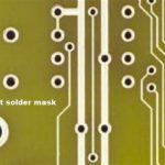
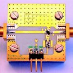
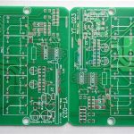
A PCB trace, also known as a PCB track or circuit trace, is a thin strip of copper or other conductive material that is etched or printed onto the surface of a printed circuit board (PCB). PCB traces are used to electrically connect different components on the board, allowing for the flow of electrical signals and power between them.
PCB traces play a crucial role in the functionality and performance of electronic devices. They are responsible for carrying electrical signals between components, such as integrated circuits (ICs), resistors, capacitors, and connectors. The design and layout of PCB traces greatly influence factors like signal integrity, electromagnetic compatibility (EMC), and power distribution.
Key Characteristics of PCB Traces
- Width: The width of a PCB trace determines its current-carrying capacity and impedance. Wider traces can handle higher currents and have lower impedance.
- Thickness: The thickness of a PCB trace affects its resistance and current-carrying capacity. Thicker traces have lower resistance and can carry more current.
- Length: The length of a PCB trace influences signal propagation delay and impedance matching. Longer traces may require impedance matching techniques to maintain signal integrity.
- Spacing: The spacing between PCB traces is important for preventing crosstalk and ensuring proper insulation. Adequate spacing helps minimize electromagnetic interference (EMI) between traces.
PCB Trace Design Considerations
When designing PCB traces, several factors need to be taken into account to ensure optimal performance and reliability. Here are some key considerations:
Current-Carrying Capacity
The current-carrying capacity of a PCB trace depends on its width, thickness, and the mAXImum allowable temperature rise. It is important to ensure that the traces are designed to handle the expected current without overheating or causing voltage drops. The following table provides a general guide for trace width based on current requirements:
| Current (A) | Trace Width (mm) |
|---|---|
| 0.5 | 0.2 |
| 1.0 | 0.4 |
| 2.0 | 0.8 |
| 3.0 | 1.2 |
| 5.0 | 2.0 |
Note: These values are approximate and may vary based on factors like copper thickness, ambient temperature, and trace length.
Impedance Matching
Impedance matching is crucial for high-speed signals to maintain signal integrity and prevent reflections. The characteristic impedance of a PCB trace depends on its geometry, dielectric constant of the PCB material, and the proximity to ground or power planes. Common impedance values for PCB traces include 50Ω, 75Ω, and 100Ω.
To achieve impedance matching, the following techniques can be used:
- Controlled Impedance traces: By precisely controlling the width, thickness, and spacing of traces, the desired characteristic impedance can be obtained.
- Termination resistors: Placing termination resistors at the end of transmission lines helps match the impedance and minimize reflections.
- Differential pairs: Using differential signaling with matched trace pairs helps cancel out common-mode noise and maintains a consistent impedance.
Crosstalk and EMI Reduction
Crosstalk occurs when signals from one trace interfere with signals on adjacent traces due to electromagnetic coupling. EMI is the unintentional emission of electromagnetic energy from electronic devices, which can cause interference in other devices.
To minimize crosstalk and EMI, consider the following:
- Adequate spacing: Maintain sufficient spacing between traces to reduce electromagnetic coupling. The spacing depends on factors like signal frequency, rise time, and trace geometry.
- Ground planes: Use ground planes to provide a low-impedance return path for signals and shield traces from external EMI.
- Shielding: Implement shielding techniques, such as grounded copper pours or shielded cables, to reduce EMI emissions and susceptibility.
- Routing techniques: Use proper routing techniques, such as avoiding parallel runs of sensitive traces, minimizing loop areas, and using guard traces or stitching vias.
Signal Integrity
Signal integrity refers to the ability of a signal to maintain its intended characteristics as it propagates through the PCB traces. Factors that affect signal integrity include:
- Trace geometry: The width, thickness, and spacing of traces influence impedance matching, crosstalk, and EMI.
- Dielectric materials: The choice of PCB Substrate material affects the dielectric constant, loss tangent, and signal propagation speed.
- Termination and matching: Proper termination and impedance matching techniques help prevent reflections and maintain signal integrity.
- Routing topology: The routing topology, such as daisy-chaining or star routing, impacts signal integrity and timing.
To ensure good signal integrity, follow these guidelines:
- Minimize trace length: Keep traces as short as possible to reduce signal propagation delay and attenuation.
- Avoid sharp bends: Use smooth bends or 45-degree angles instead of 90-degree angles to minimize reflections and impedance discontinuities.
- Match trace lengths: For critical signals or differential pairs, match the trace lengths to maintain consistent timing and avoid skew.
- Use appropriate termination: Implement proper termination techniques, such as series termination or parallel termination, based on the signal characteristics and requirements.
PCB Trace Manufacturing Techniques
PCB traces can be manufactured using various techniques, each with its own advantages and limitations. The choice of manufacturing technique depends on factors like the desired trace width, thickness, and the overall PCB Fabrication process.
Subtractive Process
The subtractive process, also known as etching, is the most common method for manufacturing PCB traces. It involves the following steps:
- Applying a photoresist layer: A light-sensitive photoresist material is applied to the copper-clad PCB substrate.
- Exposing the photoresist: The photoresist is exposed to light through a photomask that defines the trace patterns.
- Developing the photoresist: The exposed photoresist is developed, hardening the areas that will form the traces.
- Etching the copper: The unwanted copper is etched away using a chemical solution, leaving behind the desired trace patterns.
- Removing the photoresist: The remaining photoresist is stripped off, revealing the final copper traces.
The subtractive process allows for fine trace widths and is suitable for mass production. However, it has limitations in terms of minimum trace width and spacing due to the etching process.
Additive Process
The additive process, also known as printed electronics or inkjet printing, involves directly printing conductive traces onto the PCB substrate. This process uses conductive inks or pastes that are deposited onto the substrate using techniques like screen printing, inkjet printing, or aerosol jet printing.
Advantages of the additive process include:
- Reduced material waste: Since the conductive material is directly printed, there is minimal waste compared to the subtractive process.
- Flexibility in substrate choice: Additive processes can be used on a variety of substrates, including flexible materials like polymers or paper.
- Rapid prototyping: Additive processes enable quick prototyping and customization of PCB designs.
However, the additive process may have limitations in terms of trace resolution, conductivity, and durability compared to the subtractive process.
Semi-Additive Process
The semi-additive process (SAP) combines aspects of both subtractive and additive processes. It involves the following steps:
- Applying a thin copper seed layer: A thin layer of copper is deposited onto the PCB substrate.
- Patterning the traces: The desired trace patterns are defined using photoresist or other masking techniques.
- Plating the traces: Additional copper is electroplated onto the exposed copper seed layer to build up the trace thickness.
- Removing the excess copper: The unwanted copper seed layer is etched away, leaving behind the plated traces.
The semi-additive process allows for finer trace widths and higher resolution compared to the subtractive process. It is commonly used for high-density interconnect (HDI) PCBs and advanced packaging technologies.

PCB Trace Testing and Inspection
To ensure the quality and reliability of PCB traces, various testing and inspection techniques are employed during the manufacturing process and after assembly.
Visual Inspection
Visual inspection is the first step in evaluating the quality of PCB traces. It involves examining the traces under magnification to check for defects such as:
- Discontinuities: Breaks or gaps in the traces that can cause open circuits.
- Short circuits: Unintended connections between adjacent traces or to ground.
- Trace width variations: Inconsistencies in trace width that can affect impedance and current-carrying capacity.
- Etchback or undercut: Excessive removal of copper during the etching process, resulting in narrower or disconnected traces.
Visual inspection can be performed manually using microscopes or automatically using automated optical inspection (AOI) systems.
Electrical Testing
Electrical testing is performed to verify the continuity, isolation, and electrical characteristics of PCB traces. Common electrical tests include:
- Continuity test: Verifies that there is a continuous electrical path between the intended points on the PCB.
- Isolation test: Checks for unintended shorts or leakage between traces, pads, or planes.
- Resistance measurement: Measures the resistance of traces to ensure they meet the specified requirements.
- Impedance measurement: Verifies the characteristic impedance of controlled impedance traces.
- High-potential (HiPot) test: Applies a high voltage to check for insulation breakdown or leakage currents.
Electrical testing can be performed using various tools, such as multimeters, oscilloscopes, time-domain reflectometers (TDRs), and dedicated PCB testing equipment.
Automated Inspection
Automated inspection techniques are increasingly used to improve the speed, accuracy, and consistency of PCB trace inspection. Some common automated inspection methods include:
- Automated Optical Inspection (AOI): Uses computer vision and image processing algorithms to detect visual defects on the PCB surface.
- Automated X-ray Inspection (AXI): Utilizes X-ray imaging to inspect hidden or obscured traces, such as those in multi-layer PCBs.
- Flying Probe Testing: Employs movable probes to perform electrical tests at specific points on the PCB without the need for a dedicated test fixture.
- In-Circuit Testing (ICT): Uses a bed-of-nails fixture to make electrical contact with the PCB and perform comprehensive electrical tests.
Automated inspection techniques help identify manufacturing defects, ensure consistent quality, and reduce the need for manual intervention.
Frequently Asked Questions (FAQ) about PCB Traces
What is the difference between a PCB trace and a via?
A PCB trace is a conductive path on the surface of a PCB that connects components, while a via is a conductive hole that allows signals to pass through different layers of the PCB. Traces are used for horizontal connections, while vias enable vertical connections between layers.
Can PCB traces be repaired if damaged?
Yes, PCB traces can be repaired using techniques such as jumper wires, conductive epoxy, or micro-soldering. However, the success of the repair depends on factors like the extent of the damage, the accessibility of the affected area, and the skill of the technician. It is always better to prevent damage through proper handling and protection during assembly and use.
What is the minimum width of a PCB trace?
The minimum width of a PCB trace depends on the manufacturing capabilities of the PCB fabricator and the chosen fabrication technology. For standard PCBs using the subtractive process, the minimum trace width is typically around 0.1 mm (4 mil). However, advanced technologies like HDI or SAP can achieve trace widths as small as 0.05 mm (2 mil) or even smaller.
How do you calculate the current-carrying capacity of a PCB trace?
The current-carrying capacity of a PCB trace can be calculated using various formulas that take into account factors like trace width, thickness, temperature rise, and copper resistivity. One commonly used formula is the IPC-2221 standard, which provides guidelines for trace sizing based on the desired current and temperature rise. It is important to consult the relevant standards and consider the specific requirements of your application when determining the appropriate trace dimensions.
What is the purpose of a ground plane in relation to PCB traces?
A ground plane is a large copper area on a PCB layer that is connected to the ground potential. It serves several purposes in relation to PCB traces:
- Provides a low-impedance return path for signals, reducing loop inductance and improving signal integrity.
- Acts as a shield to reduce electromagnetic interference (EMI) between traces on different layers.
- Helps dissipate heat generated by components and traces, improving thermal management.
- Provides a stable reference voltage for signals and helps prevent ground bounce or voltage fluctuations.
Ground planes are essential for high-speed and noise-sensitive designs, as they help maintain signal integrity and minimize interference.
By understanding the characteristics, design considerations, manufacturing techniques, and testing methods for PCB traces, designers and engineers can create reliable and high-performance electronic devices. Proper trace design and layout are critical for ensuring signal integrity, minimizing crosstalk and EMI, and achieving the desired functionality of the PCB.


Leave a Reply