What is a Rigid-Flex PCB?
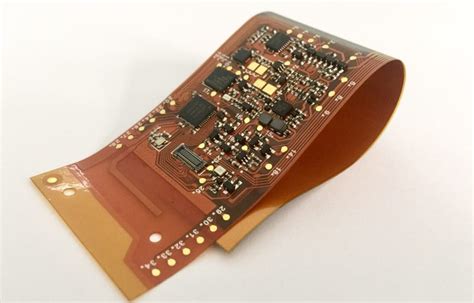
A rigid-flex PCB is a printed circuit board that combines both rigid and flexible substrates, allowing for a more compact and reliable design. The rigid parts of the board provide structural support and house the majority of the components, while the flexible portions enable the board to bend and fold, making it ideal for applications with limited space or unique packaging requirements.
Advantages of Rigid-Flex PCBs
- Space-saving design
- Improved reliability and durability
- Reduced assembly time and costs
- Enhanced signal integrity
- Increased design flexibility
Rigid-Flex PCB Manufacturing Process
The manufacturing process for rigid-flex PCBs is more complex than that of traditional rigid boards, as it involves the integration of both rigid and flexible materials. Here are the key steps in the rigid-flex PCB manufacturing process:
1. Design and Layout
The first step in the rigid-flex PCB manufacturing process is the design and layout phase. This involves creating a detailed schematic and layout of the board, taking into account the specific requirements of the application, such as the number of layers, the placement of components, and the routing of traces.
Design Considerations for Rigid-Flex PCBs
- Bend radius and flexibility requirements
- Material selection (e.g., polyimide for flexible portions)
- Layer stack-up and thickness
- Component placement and routing
- Impedance control and signal integrity
2. Material Selection and Preparation
Once the design is finalized, the next step is to select and prepare the materials for the rigid-flex PCB. This involves choosing the appropriate substrate materials for both the rigid and flexible portions of the board, as well as any additional layers, such as copper foil, adhesives, and coverlay.
Common Materials Used in Rigid-Flex PCBs
| Material | Description | Typical Thickness |
|---|---|---|
| FR-4 | Rigid substrate material | 0.2mm – 3.2mm |
| Polyimide | Flexible substrate material | 0.025mm – 0.127mm |
| Copper Foil | Conductive layer for circuitry | 18µm – 70µm |
| Adhesives | Used to bond layers together | 0.025mm – 0.05mm |
| Coverlay | Protective layer for the flexible portions | 0.025mm – 0.051mm |
3. Lamination and Bonding
The lamination and bonding process involves combining the various layers of the rigid-flex PCB to create a single, integrated board. This is done using heat and pressure to bond the layers together, ensuring a strong and reliable connection between the rigid and flexible portions.
Lamination Process Steps
- Layer stack-up and alignment
- Applying adhesives and prepreg
- Pressing and curing
4. Drilling and Plating
After lamination, the next step is to drill holes in the board for through-hole components and vias. These holes are then plated with copper to create conductive pathways between the layers of the board.
Types of Vias in Rigid-Flex PCBs
- Through-hole vias
- Blind vias
- Buried vias
- Micro vias
5. Patterning and Etching
The patterning and etching process involves creating the conductive traces on the surface of the board. This is typically done using photolithography, where a photoresist layer is applied to the board, exposed to UV light through a patterned mask, and then developed to reveal the desired circuit pattern. The exposed copper is then etched away, leaving only the desired traces.
6. Solder Mask Application and Silkscreen Printing
To protect the board and provide insulation between the conductive traces, a solder mask layer is applied to the surface of the board. This layer also helps to prevent solder bridging during the assembly process. Additionally, silkscreen printing is used to add text, logos, and other markings to the board for identification and assembly purposes.
7. Surface Finishing
The final step in the rigid-flex PCB manufacturing process is surface finishing. This involves applying a protective coating to the exposed copper traces to prevent oxidation and improve solderability. Common surface finishes include:
- HASL (Hot Air Solder Leveling)
- ENIG (Electroless Nickel Immersion Gold)
- OSP (Organic Solderability Preservative)
- Immersion Silver

Challenges in Rigid-Flex PCB Manufacturing
While rigid-flex PCBs offer numerous benefits, there are also several challenges associated with their manufacturing process:
1. Material Compatibility
Ensuring compatibility between the rigid and flexible materials used in the board is crucial for the overall performance and reliability of the final product. Proper material selection and bonding processes are essential to minimize stress and prevent delamination.
2. Bend Radius and Flexibility
Designing and manufacturing rigid-flex PCBs with the appropriate bend radius and flexibility is critical to avoid damage and ensure long-term reliability. Careful consideration must be given to the placement of components and the routing of traces in the flexible portions of the board.
3. Impedance Control
Maintaining consistent impedance throughout the board, especially in the transition areas between the rigid and flexible sections, can be challenging. Proper design techniques and manufacturing processes must be employed to minimize impedance mismatches and ensure optimal signal integrity.
4. Cost and Lead Time
Due to the complexity of the manufacturing process and the specialized materials involved, rigid-flex PCBs tend to be more expensive and have longer lead times compared to traditional rigid boards. However, the benefits they offer in terms of space savings, reliability, and performance often outweigh these challenges.

Applications of Rigid-Flex PCBs
Rigid-flex PCBs are used in a wide range of applications across various industries, including:
- Aerospace and defense
- Medical devices
- Automotive electronics
- Consumer electronics
- Industrial automation
- Wearable technology
Real-World Examples of Rigid-Flex PCB Applications
- Implantable medical devices
- Satellite and spacecraft electronics
- Automotive control modules
- Smartphones and tablets
- Robotics and automation systems

Future Trends in Rigid-Flex PCB Manufacturing
As technology continues to advance and the demand for smaller, more reliable, and high-performance electronics grows, the rigid-flex PCB manufacturing process is expected to evolve to meet these challenges. Some of the future trends in rigid-flex PCB manufacturing include:
- Increased adoption of high-density interconnect (HDI) technology
- Development of advanced materials with improved thermal and electrical properties
- Miniaturization and 3D packaging techniques
- Integration of embedded components and sensors
- Adoption of Industry 4.0 technologies, such as automation and data analytics, to optimize the manufacturing process
Frequently Asked Questions (FAQ)
1. What is the difference between a rigid-flex PCB and a traditional rigid PCB?
A rigid-flex PCB combines both rigid and flexible substrates into a single board, allowing for greater design flexibility and space savings compared to a traditional rigid PCB. The flexible portions of the board enable bending and folding, making rigid-flex PCBs ideal for applications with limited space or unique packaging requirements.
2. What materials are commonly used in rigid-flex PCBs?
Common materials used in rigid-flex PCBs include:
- FR-4: A rigid substrate material
- Polyimide: A flexible substrate material
- Copper foil: A conductive layer for circuitry
- Adhesives: Used to bond layers together
- Coverlay: A protective layer for the flexible portions
3. What are the advantages of using rigid-flex PCBs?
The main advantages of using rigid-flex PCBs include:
- Space-saving design
- Improved reliability and durability
- Reduced assembly time and costs
- Enhanced signal integrity
- Increased design flexibility
4. What industries commonly use rigid-flex PCBs?
Rigid-flex PCBs are used in various industries, including:
- Aerospace and defense
- Medical devices
- Automotive electronics
- Consumer electronics
- Industrial automation
- Wearable technology
5. Are rigid-flex PCBs more expensive than traditional rigid PCBs?
Yes, due to the complexity of the manufacturing process and the specialized materials involved, rigid-flex PCBs tend to be more expensive than traditional rigid PCBs. However, the benefits they offer in terms of space savings, reliability, and performance often justify the additional cost for many applications.
Conclusion
Rigid-flex PCBs represent a significant advancement in printed circuit board technology, offering a unique combination of durability, flexibility, and space-saving design. By understanding the key aspects of the rigid-flex PCB manufacturing process, including design considerations, material selection, and the various manufacturing steps involved, engineers and designers can leverage this technology to create innovative and high-performance electronic devices across a wide range of industries.
As technology continues to evolve, the rigid-flex PCB manufacturing process is expected to adapt and improve, enabling even greater possibilities for the future of electronic design. By staying informed about the latest trends and advancements in rigid-flex PCB manufacturing, companies can position themselves to take full advantage of this powerful technology and stay ahead of the competition in an increasingly demanding market.


Leave a Reply