No single standard covers every aspect of a ceramic PCB. Instead, engineers pull from overlapping families: IPC for design and acceptance, ASTM for substrate material properties, MIL-PRF and MIL-STD for defense qualification, and IEC/UL for safety and dielectric testing. Knowing which documents apply to your specific board prevents over-specification (and the cost that follows) as well as under-specification (and the field failures that follow).
Key Takeaways
- IPC-6012E (with Amendment 1) is the baseline acceptance standard for rigid printed boards and applies to ceramic substrates, though many of its clauses assume organic laminates and require interpretation.
- ASTM C1161 (flexural strength) and ASTM C408 (thermal conductivity) are the two most commonly referenced material test methods for ceramic substrates.
- MIL-PRF-55342 and MIL-PRF-55681 govern thick-film and thin-film resistor networks on ceramic, not the substrate itself, but they impose substrate requirements by reference.
- IEC 60664-1 sets clearance and creepage distances that determine minimum trace spacing on high-voltage ceramic boards.
- UL recognition for ceramic circuit boards follows UL 796, the same standard used for organic PCBs, with additional flammability exemptions for inorganic substrates.
IPC Standards That Apply to Ceramic PCBs
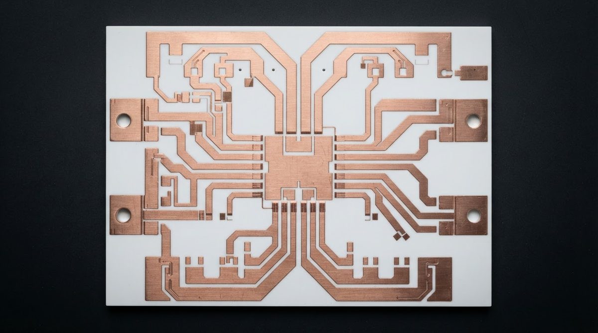
IPC standards were written primarily for FR-4 and other organic laminates. Ceramic boards inherit most requirements by analogy, but several clauses simply do not apply. The table below lists the IPC documents most frequently referenced on ceramic PCB drawings and purchase orders.
| Standard | Scope | Ceramic-Specific Notes |
|---|---|---|
| IPC-2221B | Generic standard on printed board design | Conductor spacing tables (Table 6.1) apply. Thermal relief and annular ring rules need adjustment for ceramic CTE. |
| IPC-6012E | Qualification and performance of rigid boards | Class 2 and Class 3 acceptance criteria are used. Bow-and-twist limits (Section 3.4.3) may be tighter for thin ceramic substrates. |
| IPC-A-600K | Acceptability of printed boards (visual) | Microsection criteria for plated holes are applicable to metallized vias in ceramic. Delamination criteria do not apply to monolithic substrates. |
| IPC-4101E | Specification for base materials | Does not cover ceramic. Referenced here so you know not to cite it on a ceramic drawing. |
| IPC-TM-650 | Test methods manual | Methods 2.4.8 (peel strength) and 2.6.3.7 (moisture and insulation resistance) are commonly invoked for ceramic boards with plated copper. |
Source: IPC standards library, ipc.org. Verify edition and amendment status before citing on a drawing.
A common mistake is calling out IPC-4101 on a ceramic PCB drawing. IPC-4101 covers laminate and prepreg base materials. Ceramic substrates have no equivalent IPC material specification. Material requirements should reference the substrate manufacturer’s datasheet directly, or use ASTM test methods to define acceptance limits. For a broader introduction to how these documents relate to ceramic boards, see our overview of what a ceramic PCB is.
ASTM Test Methods for Ceramic Substrate Materials
ASTM standards define how to measure the properties that matter for substrate selection: thermal conductivity, flexural strength, dielectric constant, and surface roughness. They do not set pass/fail limits. You set those on your drawing, using the ASTM method as the referee.
| Property | ASTM Method | Typical Condition | Why It Matters |
|---|---|---|---|
| Flexural strength | ASTM C1161 | 4-point bend, 20 °C | Predicts survival during assembly handling and thermal cycling |
| Thermal conductivity | ASTM E1461 (laser flash) | 25 °C, through-thickness | Determines thermal resistance of the substrate layer |
| Dielectric constant (Dk) | ASTM D150 | 1 MHz, 25 °C | Critical for RF impedance matching |
| Dielectric strength | ASTM D149 | Short-time test, 60 Hz | Sets maximum working voltage per unit thickness |
| Surface roughness (Ra) | ASTM B46.1 | Stylus profilometry | Affects adhesion of metallization and conductor loss at high frequency |
| Coefficient of thermal expansion | ASTM E228 | 25–300 °C range | Drives solder joint reliability and die-attach stress |
Methods listed are the most commonly cited in commercial ceramic substrate datasheets (CoorsTek, Kyocera, Maruwa). Confirm the specific revision and specimen geometry with your test lab.
When specifying alumina 96% substrates, for example, a typical drawing note might read: “Flexural strength ≥ 300 MPa per ASTM C1161, 4-point bend, 3 × 4 × 45 mm specimen.” That single line is unambiguous. Saying “high mechanical strength” is not.
MIL-SPECs for Defense and Aerospace Ceramic Boards
Military specifications for ceramic PCBs focus on hybrid microcircuit packaging rather than on the bare board. The most relevant documents are:
- MIL-PRF-55342 — Resistor, Fixed, Film, Chip. Specifies thick-film resistors on ceramic substrates (typically 96% Al₂O₃). Substrate requirements include minimum purity, camber, and surface finish.
- MIL-PRF-55681 — Resistor Networks, Fixed, Film. Similar scope for thin-film resistor networks on alumina or aluminum nitride.
- MIL-PRF-38534 — Hybrid Microcircuits, General Specification. Governs the complete hybrid assembly, including the ceramic substrate, metallization, die attach, and wire bonds. Class H (hermetic) and Class K (space) impose the tightest screening.
- MIL-STD-883 — Test Methods and Procedures for Microelectronics. Referenced by MIL-PRF-38534 for environmental and mechanical tests: thermal shock (Method 1011), constant acceleration (Method 2001), and fine/gross leak (Methods 1014/1071).
If your project is a standalone ceramic PCB going into a defense system but not a hybrid microcircuit, MIL-PRF-31032 (Performance Specification for Printed Wiring Boards) is the closer fit. It covers rigid boards and references IPC-6012 for most acceptance criteria. Confirm with your program’s quality engineer which document the contract actually invokes.
IEC and UL Standards for Safety and High Voltage
Ceramic substrates are common in high-voltage power modules, where safety clearances and creepage distances are governed by IEC 60664-1 and IEC 62368-1 (or the older IEC 60950-1 for IT equipment). The key advantage of ceramic over FR-4 in this context is the Comparative Tracking Index (CTI): alumina and aluminum nitride do not track, so they qualify for Material Group I (CTI ≥ 600 V) per IEC 60112, which allows shorter creepage distances at a given working voltage.
For UL listing, ceramic boards follow UL 796 (Standard for Printed-Wiring Boards). Because ceramic is inherently non-flammable, the UL 94 flammability classification required for organic laminates does not apply. The substrate still undergoes UL’s thermal endurance and dielectric withstand tests. Our page on UL certification for PCBs covers the submission process in detail.
Worked Example: Creepage Distance on a 1,200 V Ceramic Board
Per IEC 60664-1, Table F.4, for a working voltage of 1,200 V RMS, Pollution Degree 2, and Material Group I (ceramic), the minimum creepage distance is 8.0 mm. On FR-4 (Material Group IIIb, CTI < 175 V), the same voltage requires 25.0 mm. That difference directly affects how tightly you can space conductors on a power module substrate. For an aluminum nitride substrate, the same Material Group I classification applies, giving you the same 8.0 mm minimum creepage.
Cross-Reference: Standards by Application
| Application | Primary Standards | Key Requirement |
|---|---|---|
| Commercial electronics | IPC-6012E Class 2, IPC-2221B, UL 796 | Workmanship, safety listing |
| Automotive (ADAS, EV inverters) | IPC-6012E Class 3, AEC-Q200 (passives), IATF 16949 (QMS) | Zero-defect quality, PPAP documentation |
| Aerospace / defense | MIL-PRF-38534, MIL-STD-883, IPC-6012E Class 3/A, AS9100D (QMS) | Screening, lot traceability, hermeticity |
| RF / microwave | IPC-2221B, IPC-2141 (controlled impedance), MIL-PRF-55342 | Dk tolerance, conductor loss |
| High-voltage power modules | IEC 60664-1, IEC 60112, UL 796, IPC-2221B | Creepage, CTI, partial discharge |
| Medical implants | IPC-6012E Class 3, ISO 13485 (QMS), IEC 60601-1 | Biocompatibility (ISO 10993 if patient contact), reliability |
This table is a starting point. Your specific program may invoke additional or different documents. Always verify against the contract or product specification.
When Standards Do Not Cover Ceramic-Specific Issues
Several critical aspects of ceramic PCB fabrication fall into gaps between existing standards:
- Metallization adhesion. IPC-TM-650 Method 2.4.8 (peel strength) was designed for copper foil laminated to epoxy. On a DPC or DBC ceramic board, the failure mode is different: adhesion depends on the ceramic-metal interface, not a resin bond. Many manufacturers test per the IPC method anyway, but report results with a note about the failure mode (adhesive vs. cohesive).
- Via fill in ceramic. IPC-4761 covers via protection for organic boards. Ceramic vias (punched and co-fired, or laser-drilled and metallized) have no equivalent IPC document. Specify fill material, void percentage, and continuity requirements directly on your drawing.
- Substrate camber and flatness. Ceramic substrates can be significantly flatter than FR-4 (camber < 0.1 mm over 50 mm is routine for 96% alumina), but IPC-6012E's bow-and-twist limits assume organic laminates. Tighter ceramic-specific limits should be negotiated with your supplier.
When you encounter a gap, the practical approach is to write a product-specific specification that references the applicable ASTM test method and defines your own accept/reject limits. A supplier audit checklist can help you verify that your vendor tests to those limits consistently.
When You Should Not Rely on Ceramic-Specific Standards
If your board is a standard four-layer digital design running below 100 °C with no high-voltage or high-frequency requirements, FR-4 per IPC-4101 and IPC-6012 covers everything you need. Ceramic PCB standards add complexity and cost to the qualification process. They are justified only when the substrate material itself is a functional requirement: thermal conductivity above 20 W/mK, operating temperature above 300 °C, dielectric performance above 1 GHz, or high-voltage isolation with tight creepage. If none of those apply, stay with organic laminates and save yourself the documentation overhead.
Frequently Asked Questions
Is there an IPC material specification for ceramic substrates?
No. IPC-4101, which covers base materials for rigid boards, applies only to organic laminates and prepregs. Ceramic substrate material requirements should reference the manufacturer’s datasheet and ASTM test methods (e.g., ASTM C1161 for flexural strength, ASTM E1461 for thermal conductivity) directly on the fabrication drawing.
Do ceramic PCBs need UL listing?
Yes, if the end product requires a UL mark. Ceramic boards follow UL 796, the same standard as organic PCBs. The main difference is that ceramic substrates are exempt from UL 94 flammability testing because they are inherently non-combustible.
Which MIL-SPEC covers a bare ceramic PCB for defense use?
MIL-PRF-31032 is the performance specification for printed wiring boards, including rigid ceramic types. It references IPC-6012 for most acceptance criteria. If your ceramic board is part of a hybrid microcircuit, MIL-PRF-38534 governs the complete assembly instead.
Does AEC-Q100 apply to ceramic PCBs in automotive?
AEC-Q100 covers integrated circuits, not substrates. For passive components on ceramic, AEC-Q200 is the relevant document. The ceramic substrate itself is qualified through the IATF 16949 quality management system and PPAP (Production Part Approval Process) submissions agreed with the OEM.
How do I specify dielectric constant tolerance for an RF ceramic board?
Reference ASTM D150 for the test method and state the frequency, temperature, and tolerance on your drawing. A typical callout for 96% alumina at 10 GHz is Dk = 9.8 ± 0.2 at 25 °C. Confirm the achievable tolerance with your substrate supplier, as it varies by material grade and firing lot.
Next Step
If you are writing a procurement spec or drawing for a ceramic board and need to confirm which standards your supplier tests against, request a quotation with your drawing attached. Our engineering team reviews every drawing for standards compliance before quoting. Get a quote from AluminaPCB.