The right solder for ceramic PCB assemblies depends on three things: the metallization on the substrate, the peak service temperature, and the CTE mismatch between the ceramic and whatever you are attaching. For most metallized alumina boards running below 150 °C, SAC305 (Sn96.5/Ag3.0/Cu0.5) works well. For high-power modules on AlN or Si3N4 that see 200 °C+, you need high-lead (Pb90/Sn10, solidus 268 °C) or gold-tin (Au80/Sn20, solidus 280 °C) alloys. Bare, unmetallized ceramics require active solders containing titanium.
Key Takeaways
- SAC305 (melting range 217–220 °C) is the default lead-free solder for ceramic PCB assemblies in consumer and industrial applications below 150 °C continuous service.
- High-lead solder (Pb90/Sn10 or Pb95/Sn5) handles junction temperatures up to roughly 250 °C and is still permitted under RoHS exemption 7(a) for high-reliability electronics.
- Au80/Sn20 solder gives the strongest ceramic-to-metal joint (shear strength ~40 MPa per MIL-STD-883) but costs 50–100× more than SAC305 by weight.
- Active brazing alloys (e.g., Ag-Cu-Ti) wet directly to unmetallized Al2O3, AlN, and Si3N4, eliminating the need for prior thin-film or thick-film metallization.
- Flux residues left on ceramic substrates cause more field failures than wrong alloy selection; no-clean ROL0/ROL1 fluxes or full aqueous cleaning are strongly preferred.
Why Solder for Ceramic PCB Joints Demands More Care Than FR-4
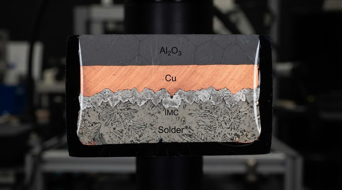
FR-4 has a CTE of roughly 14–17 ppm/°C in-plane. Common ceramics sit much lower: 96% alumina is 6.5–7.2 ppm/°C, AlN is 4.5–5.0 ppm/°C, and Si3N4 is about 2.5–3.5 ppm/°C (values per CoorsTek and Kyocera datasheets at 20–400 °C). That mismatch with copper (17 ppm/°C) or a silicon die (2.6 ppm/°C) means the solder joint absorbs significant thermomechanical strain during every power cycle.
A compliant, ductile solder like SAC305 can accommodate moderate CTE mismatch through plastic deformation. A rigid solder like Au80/Sn20 cannot flex; it relies instead on a close CTE match between the die and the substrate. Picking the wrong alloy for the mismatch in your stack leads to solder fatigue cracks, delamination, or—worst case—fracture of the ceramic itself. If you are new to ceramic circuit boards and their properties, start there before choosing an alloy.
Solder Alloys Compared: Temperature, Strength, and Cost
The table below summarizes the most common solder alloys used for ceramic PCB assembly, ranked by service temperature. Choosing the right row depends on your operating environment and metallization type.
| Alloy | Composition | Solidus / Liquidus (°C) | Max Continuous Service (°C) | Shear Strength (MPa) | Relative Cost | Typical Use |
|---|---|---|---|---|---|---|
| SAC305 | Sn96.5/Ag3.0/Cu0.5 | 217 / 220 | ~125–150 | 25–35 | 1× | LED boards, sensors, RF modules |
| Sn63/Pb37 (eutectic) | Sn63/Pb37 | 183 / 183 | ~100–125 | 20–30 | 0.8× | Legacy mil/aero, exempt products |
| Pb90/Sn10 | Pb90/Sn10 | 268 / 302 | ~200–250 | 15–25 | 1.5× | Power modules, IGBT substrates |
| Pb95/Sn5 | Pb95/Sn5 | 308 / 312 | ~250–280 | 12–20 | 1.5× | Die-attach in SiC modules |
| Au80/Sn20 | Au80/Sn20 | 280 / 280 (eutectic) | ~250 | 35–45 | 50–100× | Hermetic packages, MEMS, mil-spec |
| Ag-Cu-Ti (active braze) | Ag72/Cu28 + 2–5% Ti | 780 / 815 | ~500+ | 50–100 | 20–40× | Unmetallized ceramic-to-metal joins |
Typical values from alloy manufacturer datasheets (Indium Corp., Heraeus, Lucas-Milhaupt). Shear strength measured per ASTM D1002 or MIL-STD-883 Method 2019. Confirm against the datasheet for your specific grade.
Which Solder for Ceramic PCB Substrates by Material Type
96% and 99.6% Alumina (Al2O3)
Alumina boards are almost always metallized—thick-film silver or gold, thin-film Ti/Pt/Au, or DPC copper. Any standard solder wets to these metals. SAC305 paste is the workhorse for 99.6% alumina substrates in LED and sensor applications. For power modules that see repeated thermal cycling above 150 °C, move to Pb90/Sn10 or sintered silver paste (which is not a solder but increasingly replaces high-lead alloys).
Aluminum Nitride (AlN)
AlN substrates in high-power and UV LED applications often use DBC or AMB copper bonding. Die-attach onto the copper pad typically uses Au80/Sn20 preforms or Pb-rich solder. The low CTE of AlN (4.5–5.0 ppm/°C) closely matches SiC and GaN dies, making a rigid Au-Sn joint viable without excessive strain. SAC305 works for SMD components soldered to the topside pads, but keep reflow peak temperature below 260 °C to avoid oxidizing the AlN if any bare ceramic is exposed.
Silicon Nitride (Si3N4)
Si3N4 AMB substrates appear in traction inverters and SiC power modules. The die-attach solder here is almost universally Pb95/Sn5 or sintered silver, chosen for reliability through hundreds of thousands of –40 to +175 °C power cycles. Si3N4’s very low CTE (2.5–3.5 ppm/°C) and high fracture toughness (6–7 MPa·√m per Kyocera SN-GP datasheet) make it forgiving of rigid joints, but the solder still needs to survive the thermal swing without cracking.
Solder Paste and Flux Selection for Ceramic PCB Assembly
Paste metal content for ceramic substrates should be 88–90% by weight (Type 4 or Type 5 powder, 20–38 µm particles) to get consistent print volume on fine-pitch pads. Coarser powders leave voids more readily on the smooth ceramic surface.
Flux chemistry matters more than on FR-4. Ceramic substrates do not absorb moisture, so ionic residues from aggressive fluxes sit on the surface and create leakage paths. Use no-clean fluxes classified ROL0 or ROL1 per IPC J-STD-004B. If you must use a more active flux (for oxidized metallization, for example), clean with a full aqueous wash and verify ionic contamination below 1.56 µg/cm² NaCl equivalent per IPC-TM-650 Method 2.3.25.
For high-reliability assemblies, nitrogen inerting during reflow (O₂ < 500 ppm) reduces voiding and improves wetting. This is especially important for Au-Sn soldering, which is extremely sensitive to oxidation above 280 °C.
Enter your substrate material, metallization type, and peak operating temperature below to see which solder alloy and reflow parameters fit your design.
Worked Example: Reflow Profile for SAC305 on a DPC Alumina Board
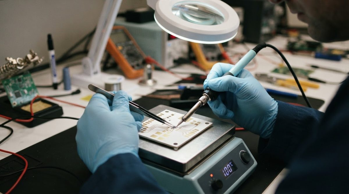
Assume a 25 × 25 mm, 0.635 mm thick 96% alumina substrate with DPC copper pads, populated with 0402 passives and a QFN-32 IC. The board’s thermal mass is low compared to a multilayer FR-4 panel, so it heats and cools faster. Getting the reflow profile right is critical when using this solder for ceramic PCB substrates that are thinner and more brittle than organic laminates.
- Preheat: Ramp at 1.5–2.0 °C/s to 150 °C. Hold 60–90 s to activate flux and equalize temperature.
- Soak: 150–200 °C for 60–120 s. Keep ΔT across the board under 10 °C to avoid thermal shock to the ceramic.
- Reflow: Ramp to peak 240–245 °C. Time above liquidus (217 °C): 45–75 s. Do not exceed 250 °C; higher peaks stress the ceramic-copper bond.
- Cooling: Cool at 2–4 °C/s. Faster cooling refines the SAC grain structure and improves fatigue life, but rates above 6 °C/s risk cracking the ceramic.
Profile parameters follow IPC-7530 guidelines for lead-free reflow. Verify your specific paste manufacturer’s recommended profile.
When Active Solder or Brazing Is Required
If the ceramic is not metallized—no copper, no silver, no gold on the surface—conventional solders will not wet it. You have two options:
- Active solders (e.g., S-Bond 220, containing titanium) that wet oxide and nitride ceramics directly at 220–250 °C in air or nitrogen. These are applied by hand or ultrasonic soldering iron, not standard reflow. Joint strength is moderate (10–20 MPa shear).
- Active brazing alloys (Ag-Cu-Ti, processed at 780–900 °C in vacuum better than 10⁻⁴ mbar). These form a strong, hermetic bond and are the basis of the AMB process used for power-module substrates. Joint shear strength can exceed 80 MPa.
Both approaches add cost and process complexity. In most cases, it is cheaper and more repeatable to specify metallized substrates from your ceramic PCB fabrication source and use conventional solder.
When Not to Use Ceramic-Specific Solders
If your board runs below 125 °C, fits on standard FR-4 or metal-core PCB, and does not need hermeticity or extreme dielectric performance, standard SAC305 on FR-4 is the right answer. Specialty solder for ceramic PCB joints adds cost with no benefit in that scenario. Similarly, if your design tolerates a CTE-matched organic substrate like Rogers RO4350B for RF work, you can avoid the brittle-substrate handling concerns entirely. Evaluate whether a ceramic board is the right choice for your project before specifying exotic alloys.
Frequently Asked Questions
Can I use regular SAC305 paste on a ceramic PCB?
Yes, as long as the ceramic has a solderable metallization layer—copper, silver, gold, or nickel. SAC305 does not wet bare ceramic. For most metallized alumina boards below 150 °C service temperature, SAC305 is the standard solder for ceramic PCB work.
Is high-lead solder still allowed under RoHS?
High-lead alloys (≥85% Pb) are exempt under RoHS Annex III, exemption 7(a), specifically for solder in high-melting-temperature applications. This exemption is reviewed periodically by the EU; as of 2024 it remains active. Always confirm the current status for your market.
Do I need a special reflow oven for ceramic substrates?
A standard convection reflow oven works for SAC305 and Pb-rich solders on metallized ceramic. The key difference is profiling: ceramics have lower thermal mass than FR-4 panels, so they heat and cool faster. Adjust ramp rates downward (≤2 °C/s preheat, ≤4 °C/s cooling) to avoid thermal shock. Au-Sn soldering requires a belt furnace with nitrogen inerting or a vacuum reflow oven.
What happens if I cool the ceramic board too fast after reflow?
Cooling rates above approximately 6 °C/s can induce microcracks in the ceramic substrate, especially in thinner boards (≤0.38 mm). The risk is highest for AlN, which has lower fracture toughness (~3 MPa·√m) than alumina (~3.5–4 MPa·√m). Keep cooling gradual and uniform.
Can I hand-solder components onto a ceramic PCB?
Yes. Use a temperature-controlled iron at 350–370 °C with a fine tip. Preheat the board to 100–150 °C on a hot plate to reduce thermal shock. Apply flux to the pad, tin the pad first, then solder the component. Avoid pressing the iron tip directly onto bare ceramic—it can cause localized cracking.
How do I store ceramic PCBs and solder paste before assembly?
Store metallized ceramic substrates in sealed, desiccated packaging at 15–30 °C and below 60% RH. Unlike FR-4, ceramics do not absorb moisture, but exposed metallization can oxidize. Solder paste follows standard IPC J-STD-005 storage rules: refrigerate at 0–10 °C, bring to room temperature 2–4 hours before use. See ceramic PCB shelf life and storage guidelines for detailed recommendations.