Introduction to Sawtooth Waves and Generators
A sawtooth wave is a basic waveform that linearly increases in amplitude before sharply dropping back down. It resembles the teeth of a saw, hence the name “sawtooth”. Sawtooth waves contain both even and odd harmonics, giving them a brighter and buzzier sound compared to pure sine waves.
Sawtooth wave generators are electronic circuits or devices that produce sawtooth waveforms. They have a wide range of applications, including:
- Sound synthesis for music production
- Test and measurement equipment
- Power electronics
- Modulation techniques in radio systems
- Time base generation for oscilloscopes and displays
Understanding how Sawtooth Generators work is important for effectively using them in circuits and systems.
Sawtooth Wave Characteristics and Parameters
A perfect sawtooth wave is defined by the following equation:
f(t) = 2A/π * arctan(cot(π*t/p))
Where:
– A is the peak amplitude
– p is the period
– t is time
However, real-world sawtooth waves are often modified or distorted versions of the ideal waveform. Key parameters that characterize sawtooth waves include:
| Parameter | Description |
|---|---|
| Amplitude | The peak-to-peak voltage of the wave |
| Frequency | The number of cycles per second (Hz) |
| Phase | Shift of the waveform relative to a reference |
| Symmetry | Ratio of rise time to fall time |
The amount of higher harmonics present determines the “sharpness” of the sawtooth’s peaks. Changing the symmetry alters the relative strength of even vs odd harmonics.

Types of Sawtooth Wave Generators
There are several ways to generate sawtooth waves in electronic circuits:
Integrator-Based Generators
An integrator circuit linearly ramps up the voltage until it reaches a threshold. The output then rapidly discharges back to the starting level. Repeating this charge-discharge cycle produces a sawtooth waveform.
Advantages:
– Simple design
– Easy to adjust frequency and amplitude
Disadvantages:
– Non-linear ramp may distort wave shape
– Requires reset circuitry for discharge
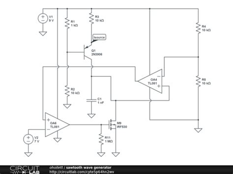
Current Source Generators
A constant current source charges a capacitor, creating a linear voltage ramp. A transistor or MOSFET switch is used to periodically short the capacitor, discharging it to generate the sawtooth flyback.
Advantages:
– Very linear ramp up
– Can generate fast rise times
Disadvantages:
– More complex than integrators
– Switch characteristics affect wave symmetry
DDS (Direct Digital Synthesis)
A digital system computes sequential amplitude values and converts them to an analog waveform using a DAC (digital-to-analog converter). DDS provides precise control over frequency, phase and shape.
Advantages:
– Highly flexible and programmable
– Extremely stable and accurate
Disadvantages:
– Requires dedicated DDS chip or FPGA
– DAC resolution limits waveform precision
Software Generation
Sawtooth waves can be mathematically computed and output via a PC sound card or DAC. This is commonly done in audio software and digital synthesizers.
Advantages:
– No additional hardware needed
– Waves easily manipulated in software
Disadvantages:
– Bandwidth limited by sound card/DAC
– Only suitable for audio-range frequencies

Designing a Transistor-Based Sawtooth Generator
Let’s walk through the steps to design a simple sawtooth generator using a transistor constant current source and switch:
-
Select the desired frequency (f), amplitude (A), and supply voltage (V+).
-
Calculate the capacitor charge time (T) based on frequency:
T = 1/f -
Determine the required charging current (I) for the target peak amplitude:
I = A/T -
Choose a capacitor (C) value, considering the supply voltage and ramp linearity:
C = I*T/V+ -
Size the current source resistor (R) to set the charging current:
R = (V+ – 0.7) / I -
Select a suitable NPN transistor and biasing resistors for the current source.
-
Add a PNP transistor switch with a short Base pulse to discharge the capacitor.
-
Buffer the sawtooth output with a high input impedance op amp or transistor stage.
Here is a sample schematic:
        +V
        |
        R
        |
        Q1
       /|\
      / | \
     /  |  \
    /   C   \
   /    |    \
  /     |     \
 /      |      \
/       |       Q2
|       |       |\
|       |       | \
|       |       |  R2
        |       |
        |       |
       GND     GND
Component values will depend on your specific design requirements.

Applications of Sawtooth Wave Generators
Audio Synthesis
Sawtooth waves are one of the most common waveforms used in analog and digital music synthesizers. Their rich harmonic content makes them well-suited for creating bright, cutting lead and bass sounds.
To produce interesting timbres, sawtooth waves are often processed with filters, envelopes, and effects. For example, applying a low pass filter with keyboard tracking can create a “sawtooth pad” sound popular in electronic music.
Many classic vintage synthesizers like the Moog Prodigy and Roland SH-101 featured sawtooth-based oscillators. Modern virtual analog synths and samplers extensively use sawtooth waves as well.
Time Base Generation
In oscilloscopes, signal generators, and other test equipment, sawtooth waves serve as linear time base signals. The sawtooth waveform is applied to the horizontal deflection system to sweep the electron beam or sampling circuitry across the screen.
Oscilloscope timebase generators must have excellent linearity and stability. Historically, this was achieved with precision integrator circuits. Modern digital scopes use DDS techniques for crystal-locked time bases.
Sawtooth-based time bases are also used in vectorscope displays, which plot a 2D Lissajous figure of relative amplitudes and phases.
PWM Motor Control
Pulse Width Modulation (PWM) is a power efficient technique for controlling the speed of brushless DC motors. A fixed-frequency sawtooth wave is compared to an adjustable DC reference voltage. The comparator output generates a variable duty cycle rectangle wave that switches the motor windings.
The sawtooth gradient, reference level, and PWM frequency determine the motor speed, torque, and efficiency. Microntrollers with built-in PWM peripherals often include a programmable sawtooth generator specifically for this purpose.
Other PWM applications for sawtooth generators include:
– Switch mode power supply control
– LED dimming circuits
– Class-D audio amplifiers
Frequency Modulation
In analog FM synthesis, a sawtooth wave modulates the frequency of another oscillator to create complex, evolving timbres. The non-linear waveshape of the sawtooth imparts a characteristic “brassiness” to the sound.
FM radio broadcasting uses a precision sawtooth generator to sweep the transmitter frequency during station identification. This allows receivers to automatically scan and lock onto the strongest signal.
Sawtooth FM is also employed in chirped radar systems and test and measurement sweeps.
FAQ
What is the difference between a sawtooth wave and a triangle wave?
A sawtooth wave ramps up linearly and then sharply drops, while a triangle wave has symmetric rising and falling linear segments. Sawtooth waves contain both even and odd harmonics, whereas triangle waves only have odd harmonics. This gives sawtooth waves a brighter, buzzier timbre compared to the more mellow sound of triangle waves.
How do I change the frequency of my sawtooth wave generator?
The frequency of a sawtooth generator is determined by the capacitor charge time, which depends on the capacitance and charging current. To increase frequency, you can either decrease the capacitance or increase the current. Adjustable-frequency generators often use a combination of switchable caps and variable current sources. DDS and software-based generators can change frequency programmatically.
Can I generate a sawtooth wave with an Arduino?
Yes, there are several ways to create sawtooth waves with an Arduino:
-
Use the analogWrite() function with a for loop to increment the output duty cycle. This produces a stepped approximation of a sawtooth.
-
Store a precomputed sawtooth waveform table in memory and output the values to a DAC or PWM pin in sequence.
-
Construct a simple RC sawtooth generator circuit and drive it with Arduino digital pins.
However, the Arduino’s limited speed and resolution will restrict the quality and frequency range of the resulting sawtooth waves. For better performance, consider using a dedicated DDS chip or DAC module.
What is the best type of sawtooth generator for audio synthesis?
For analog audio synthesis, a current source generator with a clean Switching Transistor will provide the most accurate and stable sawtooth waves. Ensure the circuit has sufficient bandwidth and low noise for the desired frequency range.
In digital or software synthesizers, wavetable or algorithmic oscillators are preferred for their flexibility and perfect repeatability. A high sample rate and bit depth will improve the fidelity of the digitally generated sawtooth.
Avoid using RC integrators or PWM for audio synthesis, as their waveforms tend to have significant distortion and aliasing artifacts.
How can I make my sawtooth generator more versatile?
Here are some ways to expand the capability of your sawtooth generator:
- Add a variable current source to adjust the frequency
- Include switches or relays to select different capacitor values
- Put a potentiometer on the output to control the amplitude
- Inject a modulation signal into the current source or switch to create FM or PWM effects
- Follow the generator with a waveshaper or filter circuit to modify the sawtooth’s harmonic content
- Synchronize multiple generators for more complex waveforms
- Interface the generator with a microcontroller or MIDI system for programmability
By understanding the core operating principles, you can customize your sawtooth generator for any application!


Leave a Reply