Introduction to Rigid-flex PCBs
Rigid-flex PCBs are a type of printed circuit board that combine rigid and flexible substrates into a single board. This innovative technology offers many advantages over traditional rigid PCBs, enabling more compact, lightweight, and reliable electronic devices. Rigid-flex PCBs are widely used in applications that require high density interconnects, 3D packaging, and dynamic flexing, such as wearables, medical devices, aerospace systems, and automotive electronics.
Key Benefits of Rigid-Flex PCBs
- Space savings and miniaturization
- Improved reliability and durability
- Reduced assembly time and costs
- Enhanced signal integrity
- Greater design flexibility
Rigid-Flex PCB Construction
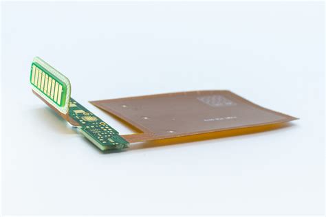
A rigid-flex PCB consists of multiple layers of flexible circuit substrates (typically polyimide) laminated together with bonding adhesives and sandwiched between rigid FR-4 boards. The rigid sections provide structural support and house surface mount components, while the flexible sections allow the board to bend and fold into 3D configurations.
Rigid-Flex PCB Layer Stackup
| Layer | Material | Thickness (mm) |
|---|---|---|
| Top Cover | Polyimide | 0.025 |
| Top Copper | Copper | 0.018 |
| Flexible Core | Polyimide | 0.050 |
| Bottom Copper | Copper | 0.018 |
| Adhesive | Acrylic | 0.050 |
| Rigid Core | FR-4 | 0.200 |
| Bottom Copper | Copper | 0.035 |
| Solder Mask | LPI | 0.015 |
The number and arrangement of layers can vary depending on the specific design requirements. Rigid-flex PCBs can have multiple flexible and rigid sections, as well as different layer counts in each section.

Rigid-Flex PCB Design Considerations
Designing a rigid-flex PCB requires careful consideration of several factors to ensure optimal performance, reliability, and manufacturability. Some key design guidelines include:
Bend Radius and Flexibility
- Minimum bend radius should be at least 6 times the total thickness of the flexible section
- Avoid placing components or vias near the bend area
- Use gradual bends instead of sharp corners
- Consider the number of flex cycles required over the product lifetime
Trace Routing and Signal Integrity
- Keep trace widths and spacing consistent across flexible and rigid sections
- Avoid routing traces perpendicular to the bend direction
- Use hatched ground planes in flexible sections to improve flexibility
- Minimize trace length and layer changes to reduce signal loss and crosstalk
Component Placement and Mounting
- Place components only on rigid sections, avoiding the flexible areas
- Use surface mount components whenever possible for lower profile and better reliability
- Provide adequate clearance between components and the board edge to prevent damage during bending
- Consider using underfill or stiffeners for large or heavy components
Coverlay and Stiffener Design
- Use coverlay to protect exposed traces and improve insulation
- Apply coverlay symmetrically on both sides of the flexible section to prevent curling
- Use stiffeners selectively to reinforce critical areas and improve flatness
- Avoid abrupt changes in stiffness which can cause stress concentrations

Rigid-Flex PCB Manufacturing Process
The manufacturing process for rigid-flex PCBs is more complex and requires specialized equipment and expertise compared to traditional rigid PCBs. The general steps involved are:
- Material preparation: cutting and cleaning the flexible and rigid substrates
- Patterning: applying and developing photoresist to define the circuit layout
- Etching: removing unwanted copper to form traces and pads
- Lamination: bonding the flexible layers together and to the rigid sections
- Drilling: creating holes for vias, through-holes, and mounting
- Plating: applying copper plating to the holes and surface to improve conductivity
- Solder mask and silkscreen: applying protective coatings and markings
- Cutting and forming: singulating individual boards and forming the final 3D shape
- Testing and inspection: verifying electrical and mechanical performance
Rigid-Flex PCB Manufacturing Challenges
- Maintaining proper alignment and registration between layers and sections
- Controlling the lamination process to prevent delamination, wrinkles, or voids
- Avoiding damage or contamination to the flexible sections during handling
- Ensuring consistent etching and plating across different materials and thicknesses
- Minimizing stress and strain during the forming and assembly process

Applications of Rigid-Flex PCBs
Rigid-flex PCBs are used in a wide range of industries and applications where size, weight, reliability, and flexibility are critical. Some common examples include:
Consumer Electronics
- Smartphones and tablets
- Wearables and smartwatches
- Virtual and augmented reality headsets
- Gaming controllers and devices
Medical Devices
- Implantable devices such as pacemakers and neurostimulators
- Diagnostic and monitoring equipment
- Surgical instruments and robotics
- Wearable health monitors and drug delivery systems
Automotive Electronics
- Advanced driver assistance systems (ADAS)
- In-vehicle infotainment and navigation systems
- Electronic control units (ECUs) and sensors
- Electric and hybrid vehicle power systems
Aerospace and Defense
- Avionics and flight control systems
- Satellite and spacecraft electronics
- Military communications and surveillance equipment
- Unmanned aerial vehicles (UAVs) and drones
Industrial and IoT
- Factory automation and robotics
- Process control and monitoring systems
- Smart sensors and actuators
- Wireless sensor networks and gateways
Rigid-Flex PCB Testing and Quality Control
Ensuring the reliability and performance of rigid-flex PCBs requires rigorous testing and quality control throughout the manufacturing process. Some common testing methods include:
Electrical Testing
- Continuity and isolation testing to verify proper connections and insulation
- Resistance and impedance testing to check for shorts, opens, and leakage
- High-potential (HiPot) testing to detect insulation breakdowns and safety hazards
- Functional Testing to validate the board’s operation under real-world conditions
Mechanical Testing
- Flexibility and bend cycle testing to evaluate the board’s durability and fatigue resistance
- Tensile and tear strength testing to measure the adhesion and cohesion of the layers
- Dimensional and visual inspection to verify the board’s geometry and appearance
- Thermal cycling and shock testing to assess the board’s performance under environmental stress
Microscopic Inspection
- Cross-sectioning analysis to examine the internal structure and interfaces
- Scanning electron microscopy (SEM) to detect micro-cracks, voids, or delamination
- Energy-dispersive X-ray spectroscopy (EDS) to identify material composition and contaminants
Reliability Testing
- Accelerated life testing to predict the board’s long-term performance and failure modes
- Humidity and temperature testing to simulate various operating environments
- Vibration and shock testing to evaluate the board’s resistance to mechanical stress
- Salt spray and corrosion testing to assess the board’s durability in harsh conditions
Future Trends in Rigid-Flex PCB Technology
As electronic devices continue to evolve and demand more functionality in smaller form factors, rigid-flex PCBs are poised to play an increasingly important role. Some emerging trends and developments in rigid-flex PCB technology include:
Advanced Materials
- High-performance polymers with improved thermal, mechanical, and electrical properties
- Thin and ultra-thin substrates for greater flexibility and bendability
- Stretchable and conformable materials for wearables and implantables
- Biodegradable and eco-friendly materials for sustainable electronics
3D Printing and Additive Manufacturing
- Direct printing of conductive traces and components on flexible substrates
- Hybrid printing of rigid and flexible sections in a single process
- Embedding of electronic components and sensors within the substrate
- Rapid prototyping and customization of rigid-flex PCBs
High-Frequency and High-Speed Applications
- Low-loss and high-speed materials for 5G, millimeter-wave, and terahertz frequencies
- Advanced shielding and grounding techniques to minimize EMI and crosstalk
- Optical interconnects and waveguides for high-bandwidth data transmission
- Integration of active and passive RF components on flexible substrates
Smart and Interactive Surfaces
- Printed sensors, antennas, and displays on flexible substrates
- Touch-sensitive and gesture-controlled interfaces
- Energy harvesting and storage devices for self-powered electronics
- Integration with artificial intelligence and machine learning algorithms
Frequently Asked Questions (FAQ)
1. What is the difference between a rigid PCB and a rigid-flex PCB?
A rigid PCB is made entirely of rigid material, typically FR-4, and cannot bend or flex. A rigid-flex PCB combines rigid and flexible sections into a single board, allowing it to be bent and folded into 3D shapes. Rigid-flex PCBs offer greater design flexibility, improved reliability, and reduced size and weight compared to rigid PCBs.
2. How many layers can a rigid-flex PCB have?
Rigid-flex PCBs can have anywhere from 2 to 40 or more layers, depending on the complexity of the design and the manufacturing capabilities of the supplier. The number of layers in the rigid and flexible sections can also vary within the same board. In general, rigid-flex PCBs tend to have fewer layers than rigid PCBs due to the challenges of laminating and flexing multiple layers.
3. What are the most common materials used in rigid-flex PCBs?
The most common materials used in rigid-flex PCBs are:
- Polyimide (PI) for the flexible substrate, due to its high heat resistance, mechanical strength, and electrical insulation properties
- FR-4 for the rigid substrate, due to its good mechanical and electrical properties, low cost, and wide availability
- Copper for the conductive traces and planes, due to its excellent electrical conductivity and thermal stability
- Acrylic or epoxy-based adhesives for bonding the layers together
Other materials such as liquid crystal polymer (LCP), polyethylene naphthalate (PEN), and polyethylene terephthalate (PET) are also used in some applications.
4. What are the key challenges in designing and manufacturing rigid-flex PCBs?
Some of the key challenges in designing and manufacturing rigid-flex PCBs include:
- Ensuring proper alignment and registration between the rigid and flexible sections during lamination and assembly
- Avoiding delamination, wrinkles, or voids in the flexible sections due to thermal or mechanical stress
- Maintaining consistent etching and plating across different materials and thicknesses
- Minimizing signal loss, crosstalk, and EMI in high-speed or high-frequency applications
- Preventing damage or contamination to the flexible sections during handling, bending, or folding
- Validating the long-term reliability and durability of the board under various environmental and operational conditions
Overcoming these challenges requires careful design, material selection, process control, and testing to ensure the optimal performance and quality of the final product.
5. What are the most important factors to consider when choosing a rigid-flex PCB supplier?
When choosing a rigid-flex PCB supplier, some of the most important factors to consider include:
- Technical capabilities and experience in designing and manufacturing rigid-flex PCBs
- Quality control and testing procedures to ensure the reliability and consistency of the boards
- Turnaround time and capacity to meet your production schedule and volume requirements
- Communication and support to address your questions, concerns, and customization needs
- Certifications and compliance with industry standards and regulations, such as ISO, UL, and RoHS
- Pricing and cost structure that fits your budget and provides good value for money
- Reputation and references from other customers in your industry or application area
By carefully evaluating these factors and selecting a reputable and capable supplier, you can ensure the success and quality of your rigid-flex PCB project.


Leave a Reply