Introduction to PWB
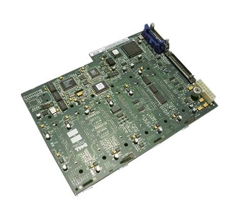
A Printed Wiring Board (PWB), also known as a Printed Circuit Board (PCB), is a fundamental component in modern electronic devices. It serves as a base for mounting and interconnecting electronic components, such as resistors, capacitors, integrated circuits, and connectors. PWBs are designed to provide electrical connections between components while ensuring proper insulation and minimizing interference.
History of PWB
The concept of printed wiring boards dates back to the early 20th century. In 1903, Albert Hanson, a German inventor, filed a patent for a method of creating an electrical connection by printing conductive traces on an insulating material. However, it wasn’t until the 1940s that the technology gained widespread adoption.
During World War II, the demand for compact and reliable electronic devices surged, leading to the development of the first practical printed wiring boards. These early PWBs were made using a subtractive process, where a layer of copper was etched away to create the desired conductive patterns.
PWB Manufacturing Process
The manufacturing process of PWBs has evolved over the years, incorporating advanced techniques and materials to meet the increasing demands of the electronics industry. The basic steps involved in PWB manufacturing are as follows:
-
Design and Layout: The first step is to create a detailed design and layout of the PWB using specialized software. The design includes the placement of components, routing of conductive traces, and the overall dimensions of the board.
-
Substrate Preparation: The substrate, typically made of a dielectric material such as FR-4 (a composite of fiberglass and epoxy resin), is cleaned and prepared for the subsequent processes.
-
Copper Cladding: A thin layer of copper is laminated onto the substrate using heat and pressure. The copper layer serves as the conductive material for the traces and pads.
-
Patterning: The desired conductive pattern is transferred onto the copper layer using a photolithographic process. A photoresist layer is applied, exposed to light through a photomask, and developed to create the desired pattern.
-
Etching: The exposed copper areas are etched away using a chemical solution, leaving behind the desired conductive traces and pads.
-
Drilling: Holes are drilled through the board to accommodate through-hole components and provide electrical connections between layers in multi-layer PWBs.
-
Plating: The holes are plated with copper to ensure electrical connectivity between layers. Additional surface finishes, such as solder mask and silkscreen, may be applied to protect the board and improve solderability.
-
Surface Mount Assembly: Surface mount components are placed onto the PWB using automated pick-and-place machines. The components are then soldered onto the pads using reflow soldering techniques.
-
Through-Hole Assembly: Through-hole components are inserted into the drilled holes and soldered onto the board using Wave Soldering or manual Soldering Methods.
-
Inspection and Testing: The assembled PWB undergoes various inspections and tests to ensure proper functionality, reliability, and adherence to quality standards.
PWB Materials
The choice of materials used in PWB manufacturing plays a crucial role in determining the performance, reliability, and cost of the final product. The primary materials used in PWBs include:
Substrate Materials
The substrate is the base material on which the conductive traces and components are mounted. Common substrate materials include:
-
FR-4: A composite material made of fiberglass and epoxy resin, FR-4 is the most widely used substrate material for PWBs. It offers good mechanical strength, electrical insulation, and thermal stability.
-
Polyimide: Polyimide substrates are known for their excellent thermal resistance and flexibility. They are commonly used in high-temperature applications and flexible electronics.
-
Ceramic: Ceramic substrates, such as alumina and beryllia, are used in high-frequency and high-power applications due to their excellent thermal conductivity and low dielectric loss.
Conductive Materials
The conductive traces and pads on PWBs are typically made of copper due to its excellent electrical conductivity and relatively low cost. Other conductive materials used in specialized applications include:
-
Silver: Silver is used in high-frequency applications due to its superior conductivity compared to copper.
-
Gold: Gold-plated traces and pads are used in applications that require high corrosion resistance and improved solderability.
Solder Mask and Silkscreen
Solder mask is a protective layer applied over the copper traces to prevent short circuits and improve the solderability of the pads. It is typically made of a polymer material and is available in various colors, with green being the most common.
Silkscreen is a layer of text and symbols printed onto the PWB to provide information such as component designators, polarity markers, and company logos. It is usually printed in white or yellow color.

PWB Design Considerations
Designing a PWB involves several key considerations to ensure optimal performance, reliability, and manufacturability. Some of the important factors to consider include:
Signal Integrity
Signal integrity refers to the ability of the PWB to transmit signals accurately and reliably. Factors that affect signal integrity include:
-
Trace width and spacing: The width and spacing of the conductive traces should be carefully designed to minimize crosstalk and maintain proper impedance.
-
Via placement: Vias, which are conductive holes that connect different layers of the PWB, should be strategically placed to minimize signal reflections and maintain signal integrity.
-
Grounding and shielding: Proper grounding and shielding techniques should be employed to reduce electromagnetic interference (EMI) and ensure stable signal transmission.
Thermal Management
PWBs generate heat during operation due to the power dissipation of the components. Effective thermal management is essential to prevent overheating and ensure reliable performance. Thermal management techniques include:
-
Copper pours: Large areas of copper, known as copper pours, can be added to the PWB to improve heat dissipation.
-
Thermal vias: Thermal vias are used to transfer heat from the components to the other side of the board or to a heatsink.
-
Component placement: Components should be placed in a way that minimizes thermal hotspots and allows for adequate airflow.
Manufacturing Considerations
Designing a PWB with manufacturability in mind can help reduce costs and improve yields. Some key manufacturing considerations include:
-
Design for Manufacturing (DFM): DFM guidelines should be followed to ensure that the PWB can be efficiently manufactured using standard processes and equipment.
-
Panelization: PWBs are often manufactured in panels to maximize throughput. Proper panelization techniques should be used to minimize waste and ensure consistent quality.
-
Testability: The PWB should be designed with testability in mind, incorporating test points and other features that facilitate automated testing and inspection.

PWB Testing and Inspection
Thorough testing and inspection are critical to ensuring the quality and reliability of PWBs. Various methods are used to verify the functionality, durability, and conformance to specifications. Some common testing and inspection techniques include:
Automated Optical Inspection (AOI)
AOI uses high-resolution cameras and image processing algorithms to inspect the PWB for defects such as missing components, Solder Bridges, and incorrect component placement. AOI systems can quickly scan the entire board and identify potential issues.
X-Ray Inspection
X-ray inspection is used to examine the internal structure of the PWB, particularly for hidden solder joints and vias. It can detect defects such as voids, cracks, and insufficient solder coverage.
In-Circuit Testing (ICT)
ICT involves using a bed-of-nails fixture to make electrical contact with specific points on the PWB. It allows for testing of individual components and circuits to verify their functionality and performance.
Functional Testing
Functional testing involves powering up the PWB and running it through a series of operational tests to ensure that it performs as intended. This may include testing various inputs, outputs, and communication interfaces.
Environmental Testing
Environmental testing exposes the PWB to various environmental conditions, such as temperature, humidity, and vibration, to assess its durability and reliability. This helps identify potential weaknesses and ensures that the PWB can withstand the intended operating conditions.

PWB Industry Trends
The PWB industry is constantly evolving, driven by advances in technology and changing market demands. Some of the key trends shaping the PWB industry include:
Miniaturization
The trend towards smaller and more compact electronic devices has led to a demand for miniaturized PWBs. This involves using finer pitch components, thinner substrates, and advanced packaging techniques such as chip-on-board (COB) and package-on-package (PoP).
High-Speed and High-Frequency Applications
The increasing demand for high-speed data transmission and wireless communication has driven the development of PWBs that can operate at higher frequencies. This requires the use of advanced materials with low dielectric loss, such as low-loss laminates and high-frequency substrates.
Flexible and Stretchable PWBs
Flexible and stretchable PWBs are gaining popularity in applications such as wearable electronics, medical devices, and automotive systems. These PWBs use flexible substrates and specialized materials to allow for bending, folding, and stretching without compromising electrical performance.
Sustainable and Eco-Friendly Materials
There is a growing emphasis on using sustainable and eco-friendly materials in PWB manufacturing. This includes the use of halogen-free flame retardants, lead-free solders, and recyclable substrate materials. Efforts are also being made to reduce waste and minimize the environmental impact of PWB production.
Industry 4.0 and Automation
The PWB industry is embracing Industry 4.0 technologies, such as the Internet of Things (IoT), big data analytics, and artificial intelligence, to optimize manufacturing processes and improve efficiency. Automated systems, such as robotic assembly lines and intelligent inspection systems, are being deployed to enhance productivity and quality control.
Frequently Asked Questions (FAQ)
-
Q: What is the difference between a PWB and a PCB?
A: PWB (Printed Wiring Board) and PCB (Printed Circuit Board) are often used interchangeably. They refer to the same thing – a board that provides electrical connections and mechanical support for electronic components. -
Q: What are the advantages of using a multi-layer PWB?
A: Multi-layer PWBs offer several advantages, including increased component density, improved signal integrity, reduced electromagnetic interference, and better thermal management. They allow for more complex designs and higher performance compared to single-layer PWBs. -
Q: What is the purpose of solder mask on a PWB?
A: Solder mask is a protective layer applied to the copper traces on a PWB. It serves several purposes, including preventing short circuits, protecting the traces from oxidation and contamination, and providing electrical insulation. Solder mask also improves the solderability of the pads by defining the areas where solder should be applied. -
Q: How can I ensure the reliability of my PWB design?
A: To ensure the reliability of your PWB design, consider the following factors: - Follow design for manufacturing (DFM) guidelines to ensure manufacturability and minimize defects.
- Use appropriate materials and components that meet the required specifications and standards.
- Implement proper signal integrity techniques, such as impedance matching and crosstalk reduction.
- Conduct thorough testing and inspection to identify and address any potential issues.
-
Consider the operating environment and incorporate necessary protections against environmental factors such as temperature, humidity, and vibration.
-
Q: What are the environmental considerations in PWB manufacturing?
A: PWB manufacturing involves the use of various chemicals and materials that can have an environmental impact. To minimize the environmental footprint, consider the following: - Use eco-friendly materials, such as halogen-free flame retardants and lead-free solders.
- Implement proper waste management and disposal practices to prevent contamination of air, water, and soil.
- Optimize the manufacturing process to reduce energy consumption and minimize waste.
- Comply with relevant environmental regulations and standards, such as RoHS (Restriction of Hazardous Substances) and REACH (Registration, Evaluation, Authorization, and Restriction of Chemicals).
Conclusion
Printed Wiring Boards (PWBs) are essential components in modern electronics, providing the foundation for interconnecting and supporting electronic components. The manufacturing process of PWBs involves various steps, from design and layout to assembly and testing, each contributing to the overall quality and reliability of the final product.
The choice of materials, design considerations, and testing methods play a crucial role in determining the performance and durability of PWBs. As the electronics industry continues to evolve, trends such as miniaturization, high-speed applications, flexible electronics, and sustainable manufacturing are shaping the future of PWB technology.
By understanding the fundamentals of PWBs, staying updated with industry trends, and following best practices in design and manufacturing, engineers and manufacturers can create reliable and high-performance electronic products that meet the ever-increasing demands of the market.


Leave a Reply