Introduction to PCB Layout
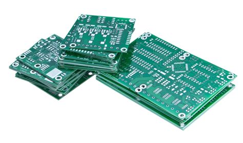
Printed Circuit Board (PCB) layout is a crucial step in the electronic product development process. It involves the arrangement of electronic components and the design of the conductive pathways that connect them on a PCB. A well-designed PCB layout ensures proper functionality, reliability, and manufacturability of the electronic device.
The Importance of PCB Layout Design
PCB layout design plays a vital role in the overall performance and success of an electronic product. Here are some reasons why PCB layout is essential:
-
Functionality: A properly designed PCB layout ensures that the electronic components are connected correctly, enabling the device to function as intended.
-
Signal Integrity: PCB layout design considers factors such as trace width, spacing, and impedance matching to maintain the integrity of electrical signals, minimizing issues like crosstalk, reflections, and electromagnetic interference (EMI).
-
Thermal Management: Effective PCB layout design helps in managing the heat generated by electronic components, preventing overheating and ensuring optimal performance.
-
Manufacturability: A well-designed PCB layout takes into account manufacturing constraints and guidelines, making it easier and more cost-effective to produce the PCB.
-
Reliability: Proper PCB layout design enhances the reliability of the electronic device by minimizing potential failures due to factors like mechanical stress, vibrations, and environmental conditions.
PCB Layout Design Process
The PCB layout design process involves several steps, each requiring careful consideration and attention to detail. Here’s an overview of the typical PCB layout design process:
1. Schematic Design
The first step in PCB layout design is to create a schematic diagram of the electronic circuit. The schematic represents the logical connections between the electronic components and serves as a blueprint for the PCB layout.
2. Component Placement
Once the schematic is finalized, the next step is to place the electronic components on the PCB. The placement of components is critical for several reasons:
- Functionality: Components must be placed in a way that allows for proper electrical connections and signal flow.
- Thermal Management: Heat-generating components should be placed strategically to ensure adequate heat dissipation.
- Mechanical Considerations: Component placement should consider mechanical constraints such as mounting holes, connectors, and enclosure dimensions.
3. Routing
After component placement, the next step is to route the conductive traces that connect the components. Routing is a complex process that involves several considerations:
- Signal Integrity: Traces must be routed to maintain signal integrity, minimizing crosstalk, reflections, and EMI.
- Impedance Matching: Traces must be designed with the appropriate width and spacing to achieve the desired impedance for high-speed signals.
- Manufacturing Constraints: Routing must adhere to manufacturing guidelines, such as minimum trace width and spacing, to ensure manufacturability.
4. Design Rule Check (DRC)
Once the routing is complete, a Design Rule Check (DRC) is performed to ensure that the PCB layout adheres to the design rules and manufacturing constraints. The DRC checks for issues such as:
- Minimum trace width and spacing violations
- Clearance violations between components and traces
- Unconnected or short-circuited traces
5. Gerber File Generation
After the PCB layout passes the DRC, the final step is to generate the Gerber files. Gerber files are the industry-standard format used by PCB manufacturers to fabricate the PCB. The Gerber files contain all the necessary information, including the copper layers, solder mask, silkscreen, and drill data.
Considerations for PCB Layout Design
To ensure a successful PCB layout design, several key considerations must be taken into account:
1. Signal Integrity
Signal integrity is a critical aspect of PCB layout design, especially for high-speed and high-frequency circuits. Factors that impact signal integrity include:
- Trace Width and Spacing: Traces must be designed with the appropriate width and spacing to minimize crosstalk and maintain the desired impedance.
- Grounding and Shielding: Proper grounding and shielding techniques should be employed to minimize EMI and ensure a clean signal environment.
- Termination and Impedance Matching: High-speed signals may require termination and impedance matching techniques to minimize reflections and ensure signal integrity.
2. Thermal Management
Effective thermal management is essential to ensure the reliability and longevity of electronic components. PCB layout design plays a crucial role in thermal management:
- Component Placement: Heat-generating components should be placed strategically to ensure adequate heat dissipation and avoid thermal hot spots.
- Copper Pour: Adding copper pour on unused areas of the PCB can help in heat dissipation and improve thermal performance.
- Thermal Vias: Thermal vias can be used to transfer heat from components to other layers of the PCB or to an external heatsink.
3. EMI and EMC
Electromagnetic Interference (EMI) and Electromagnetic Compatibility (EMC) are important considerations in PCB layout design. To minimize EMI and ensure EMC compliance, the following techniques can be employed:
- Shielding: Shielding sensitive components or areas of the PCB can help in reducing EMI.
- Ground Planes: Using solid ground planes can provide a low-impedance return path for high-frequency signals and help in minimizing EMI.
- Decoupling Capacitors: Placing decoupling capacitors close to the power pins of integrated circuits can help in reducing high-frequency noise and improving EMC performance.
4. Manufacturing Considerations
PCB layout design must take into account manufacturing constraints and guidelines to ensure the manufacturability and reliability of the PCB. Some key manufacturing considerations include:
- Minimum Trace Width and Spacing: PCB manufacturers have specific guidelines for minimum trace width and spacing based on the PCB technology and manufacturing capabilities.
- Drill Sizes and Pad Dimensions: The drill sizes for vias and the dimensions of component pads must adhere to manufacturing guidelines to ensure proper fabrication and assembly.
- Solder Mask and Silkscreen: The solder mask and silkscreen layers should be designed with appropriate clearances and tolerances to ensure accurate application during the manufacturing process.

PCB Layout Design Tools
Several software tools are available for PCB layout design, offering a range of features and capabilities. Some popular PCB layout design tools include:
-
Altium Designer: Altium Designer is a comprehensive PCB design tool widely used in the industry. It offers advanced features for schematic capture, PCB layout, and 3D modeling.
-
Cadence Allegro: Cadence Allegro is a powerful PCB design solution used for complex and high-speed designs. It provides a rich set of tools for constraint-driven PCB layout and signal integrity analysis.
-
KiCad: KiCad is a free and open-source PCB design tool that has gained popularity among hobbyists and small businesses. It offers schematic capture, PCB layout, and 3D viewer capabilities.
-
Eagle: Eagle is a widely used PCB design tool, particularly among hobbyists and small-scale projects. It provides a user-friendly interface and a large community-contributed library of components and designs.
-
OrCAD: OrCAD is a comprehensive PCB design solution offered by Cadence. It includes schematic capture, PCB layout, and simulation tools, making it suitable for a wide range of electronic design applications.
| Tool | Manufacturer | Key Features |
|---|---|---|
| Altium Designer | Altium | Advanced schematic capture, PCB layout, 3D modeling |
| Cadence Allegro | Cadence | Constraint-driven PCB layout, signal integrity analysis |
| KiCad | Open Source | Free, schematic capture, PCB layout, 3D viewer |
| Eagle | Autodesk | User-friendly interface, large community-contributed library |
| OrCAD | Cadence | Schematic capture, PCB layout, simulation tools |
PCB Layout Design Services
For businesses and individuals who lack the expertise or resources to design PCB layouts in-house, there are professional PCB layout design services available. These services offer several benefits:
-
Expertise: PCB layout design services have experienced engineers who specialize in PCB layout and are well-versed in industry standards and best practices.
-
Time and Cost Savings: Outsourcing PCB layout design can save time and costs associated with hiring and training in-house personnel, as well as investing in expensive PCB design tools.
-
Quality Assurance: Professional PCB layout design services follow rigorous quality assurance processes to ensure the designed PCB meets the required specifications and manufacturing guidelines.
-
Scalability: PCB layout design services can handle projects of varying scales and complexities, from simple single-layer boards to complex multi-layer designs.
When choosing a PCB layout design service, consider factors such as their experience, expertise in your specific industry or application, turnaround time, communication, and pricing. It’s also important to ensure that the service provider follows industry standards and has a proven track record of successful PCB layouts.
Conclusion
PCB layout design is a critical aspect of electronic product development, impacting the functionality, reliability, and manufacturability of the final product. A well-designed PCB layout ensures proper signal integrity, thermal management, and EMC compliance while adhering to manufacturing constraints and guidelines.
The PCB layout design process involves several steps, including schematic design, component placement, routing, design rule checking, and Gerber file generation. Each step requires careful consideration of various factors to ensure a successful PCB layout.
Professional PCB layout design services offer expertise, time and cost savings, quality assurance, and scalability for businesses and individuals who require PCB layout design. By outsourcing PCB layout design to experienced professionals, companies can focus on their core competencies while ensuring high-quality PCB designs for their electronic products.
Frequently Asked Questions (FAQ)
-
What is PCB layout design?
PCB layout design is the process of arranging electronic components and designing the conductive pathways that connect them on a Printed Circuit Board (PCB). It involves considerations such as component placement, routing, signal integrity, thermal management, and manufacturability. -
Why is PCB layout design important?
PCB layout design is crucial for the proper functionality, reliability, and manufacturability of electronic devices. It ensures that the components are connected correctly, signals maintain their integrity, thermal management is effective, and the PCB can be manufactured efficiently and cost-effectively. -
What are the key steps in the PCB layout design process?
The key steps in the PCB layout design process include: - Schematic design: Creating a logical representation of the electronic circuit.
- Component placement: Arranging the electronic components on the PCB.
- Routing: Designing the conductive traces that connect the components.
- Design Rule Check (DRC): Verifying that the PCB layout adheres to design rules and manufacturing constraints.
-
Gerber file generation: Generating the industry-standard files used for PCB fabrication.
-
What are some important considerations in PCB layout design?
Important considerations in PCB layout design include: - Signal integrity: Ensuring the integrity of electrical signals by proper trace design, grounding, and shielding.
- Thermal management: Managing the heat generated by electronic components through strategic component placement, copper pour, and thermal vias.
- EMI and EMC: Minimizing electromagnetic interference and ensuring electromagnetic compatibility through shielding, ground planes, and decoupling capacitors.
-
Manufacturing constraints: Adhering to manufacturing guidelines for trace width, spacing, drill sizes, and pad dimensions.
-
What are the benefits of using professional PCB layout design services?
The benefits of using professional PCB layout design services include: - Expertise: Access to experienced engineers who specialize in PCB layout design.
- Time and cost savings: Outsourcing PCB layout design can save time and costs associated with in-house personnel and tools.
- Quality assurance: Professional services follow rigorous quality assurance processes to ensure the designed PCB meets specifications and manufacturing guidelines.
- Scalability: PCB layout design services can handle projects of varying scales and complexities.


Leave a Reply