LTCC Definition: What Is Low Temperature Co-Fired Ceramic?
The LTCC definition in one sentence: LTCC (Low Temperature Co-Fired Ceramic) is a multilayer ceramic substrate technology in which glass-ceramic green tapes are laminated, patterned with conductors, and co-fired at 850–900 °C. Because the firing temperature stays below the melting point of silver (961 °C) and gold (1 064 °C), these low-resistivity metals can be embedded directly inside the ceramic stack during a single firing cycle. Understanding this LTCC definition is essential for engineers evaluating RF, sensor, or hermetic packaging substrates.
How LTCC Differs from HTCC
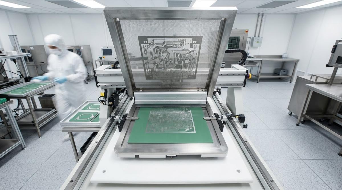
HTCC (High Temperature Co-Fired Ceramic) fires alumina-based tapes at 1 500–1 600 °C. At those temperatures, silver and gold melt, so HTCC is limited to refractory conductors such as tungsten or molybdenum, which have 3–5× higher resistivity. The lower firing temperature central to the LTCC definition is its key advantage: silver paste has a bulk resistivity of roughly 1.6 µΩ·cm versus about 5.5 µΩ·cm for tungsten, making LTCC far better suited to RF and high-frequency circuits where conductor loss matters.
Key Material Properties of LTCC
| Parameter | Typical LTCC Range | Unit | Condition / Source |
|---|---|---|---|
| Dielectric constant (εr) | 5.0–9.0 | — | 1 MHz–10 GHz; per DuPont 951 / Ferro A6M datasheets |
| Loss tangent (tan δ) | 0.001–0.006 | — | 1–10 GHz |
| Thermal conductivity | 2–4 | W/mK | 25 °C; ASTM E1461 |
| CTE | 5.0–7.0 | ppm/°C | 25–300 °C |
| Flexural strength | 200–320 | MPa | ASTM C1161 |
| Co-fired conductor | Ag, Au, Ag/Pd | — | — |
| Firing temperature | 850–900 | °C | Peak, air atmosphere |
Typical values for commercially available material, for comparison only. Confirm against the datasheet for your specific grade.
Note the low thermal conductivity of 2–4 W/mK. By the LTCC definition, the glass-ceramic matrix trades thermal performance for RF-friendly dielectric properties. Alumina (24–28 W/mK) and AlN (170–200 W/mK) are far better heat spreaders. Silver-filled thermal vias partially compensate, but LTCC is not the right choice for high-power-density applications where bulk conduction through the substrate matters.
Enter your substrate thickness, via density, and dissipated power below to estimate how temperature rise changes with different LTCC stackup configurations.
Basic LTCC Process Steps
- Tape casting — Glass-ceramic slurry is cast into thin green tapes (50–250 µm per layer).
- Via punching — Mechanical or laser drilling creates via holes.
- Via filling and screen printing — Silver or gold paste fills vias and prints conductor patterns on each layer.
- Lamination — Layers are stacked and pressed (typically 20–25 MPa at 70 °C).
- Sintering — The laminated stack is co-fired at 850–900 °C in air. Ceramic and conductors densify together.
- Post-fire processing — Optional surface finishes, trimming, or component attachment.
This single co-firing step is what separates the LTCC definition from post-fired thick-film processes, where conductors are printed and fired onto an already-sintered substrate in multiple separate passes.
Typical Applications
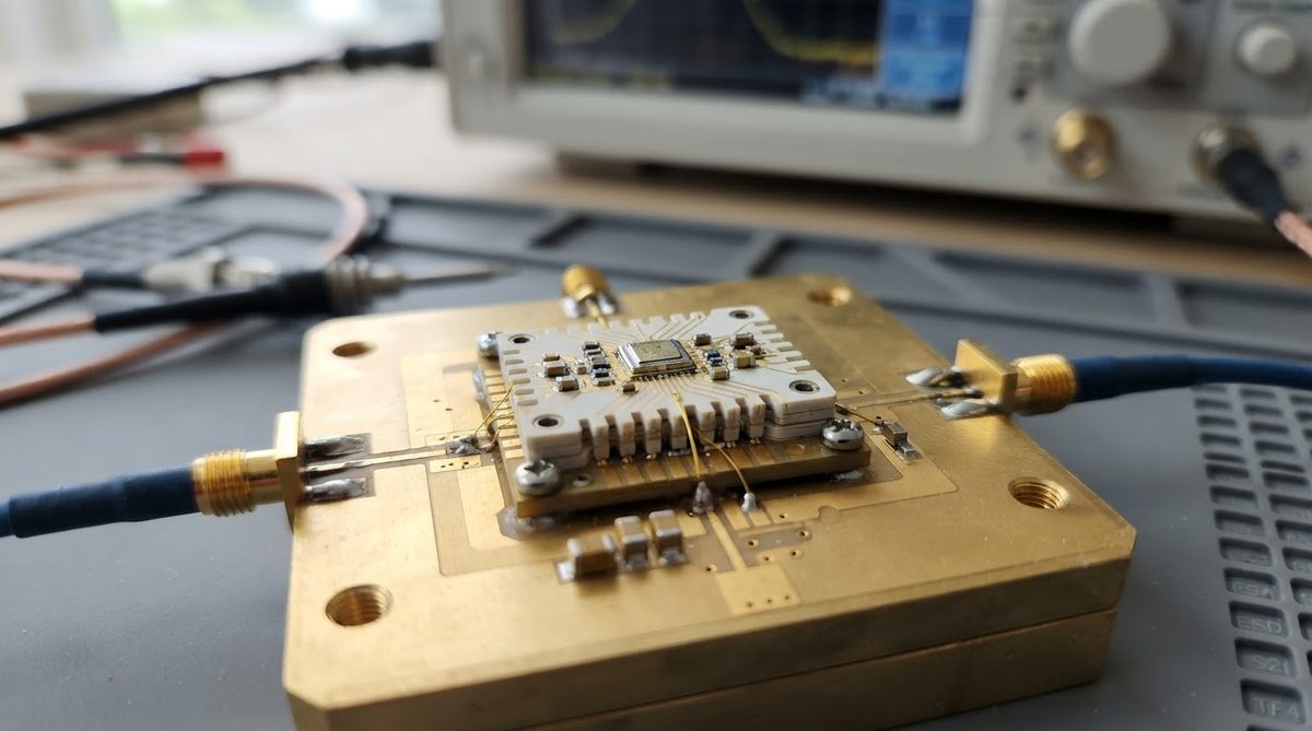
LTCC is widely used where multilayer RF routing, hermetic packaging, or embedded passives (capacitors, inductors, filters) are needed in a compact footprint. Common applications include automotive radar modules (77 GHz), satellite communication front-ends, MEMS sensor packages, and medical implant electronics.
When LTCC Is Not the Right Choice
If your primary requirement is thermal dissipation, the 2–4 W/mK thermal conductivity inherent to the LTCC definition is a serious limitation. DBC on alumina or AlN substrates are better options for power electronics. If your design is single- or double-layer with no embedded passives, standard thick-film or thin-film on alumina is simpler and cheaper. And for cost-sensitive, high-volume consumer products with moderate frequency requirements, FR-4 or Rogers organic laminates usually win on price.
FAQ
What does LTCC stand for?
LTCC stands for Low Temperature Co-Fired Ceramic. The “co-fired” part means the ceramic body and metal conductors are sintered in a single firing step, which is the core of the LTCC definition.
What is the maximum number of layers in an LTCC stack?
Production LTCC modules commonly reach 20–40 layers. Some aerospace and defense designs exceed 50 layers, though warpage control and via registration become increasingly difficult above 30.
Can LTCC be used above 300 °C?
Yes. The glass-ceramic body itself is stable to well above 600 °C. The practical limit depends on the conductor metallurgy and any attached components, not the substrate.
Is LTCC hermetic?
Fully densified LTCC is hermetic. Helium leak rates below 1 × 10⁻⁸ atm·cm³/s are routinely achieved, meeting MIL-STD-883 Method 1014 requirements for sealed packages.