Blog
-
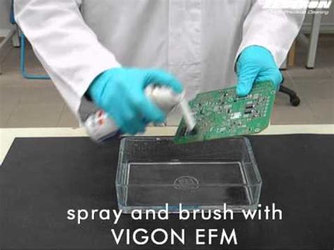
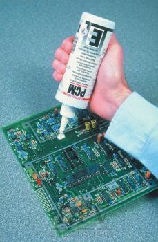
How to Clean PCBs after Surface Mount Soldering
Posted by
–
Read more: How to Clean PCBs after Surface Mount SolderingIntroduction to PCB Cleaning Printed Circuit Boards (PCBs) are essential components in modern electronics. After the surface mount soldering process, it is crucial to clean the PCBs to ensure optimal performance and longevity. Proper cleaning removes flux residues, solder spatters, and other contaminants that can lead to corrosion, short circuits, […]
-
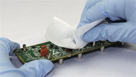 Read more: Dirty PCB – The Ultimate Guide To Make Your PCB Clean And Durable
Introduction Printed circuit boards (PCBs) are essential components in virtually all modern electronic devices. Over time, PCBs can accumulate dust, dirt, flux residue, and other contaminants that can degrade their performance and shorten their lifespan. Properly cleaning and maintaining your PCBs is crucial to ensure optimal functionality and durability. In […]
-
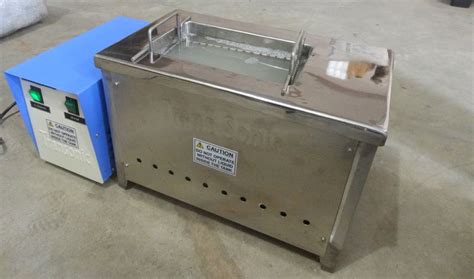
Ultrasonic PCB Cleaner-How To Use It
Posted by
–
 Read more: Ultrasonic PCB Cleaner-How To Use It
Introduction to Ultrasonic PCB cleaners An ultrasonic PCB cleaner is a device that uses high-frequency sound waves to clean printed circuit boards (PCBs) and other electronic components. This cleaning method is highly effective in removing flux residues, dirt, grease, and other contaminants from the surface of PCBs without causing any […]
-
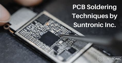
How To Make a Good PCB Solder Ball
Posted by
–
 Read more: How To Make a Good PCB Solder Ball
Introduction to PCB Soldering Printed Circuit Board (PCB) soldering is a crucial process in electronics manufacturing that involves joining electronic components to the copper pads on a PCB using molten solder. One important aspect of PCB soldering is creating good solder balls, which ensure strong and reliable connections between components […]
-
 Read more: What is Peelable Solder Mask in PCB Manufacturing
Introduction to Peelable Solder Mask Peelable solder mask (PSM) is a specialized type of solder mask used in printed circuit board (PCB) manufacturing. It is a temporary protective coating applied to specific areas of a PCB during the soldering process, providing a barrier against solder bridging and ensuring precise solder […]
-
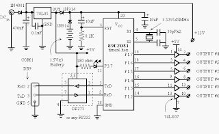
How to Creat a Microcontroller Circuit Board
Posted by
–
 Read more: How to Creat a Microcontroller Circuit Board
Introduction to Microcontroller Circuits A microcontroller is a small, self-contained computer that is designed to control a specific task or set of tasks. It is a type of integrated circuit that contains a processor, memory, and input/output peripherals, all on a single chip. Microcontrollers are widely used in embedded systems, […]
-
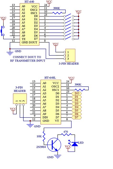 Read more: HT12D: A Guide on an RF Decoder IC for Remote Control Applications
Introduction to the HT12D RF Decoder The HT12D is a popular radio frequency (RF) decoder integrated circuit (IC) used in many wireless remote control applications. Manufactured by Holtek, this 2^12 series decoder pairs with Holtek’s HT12E RF encoder to form a complete RF transmitter and receiver solution for controlling devices […]
-
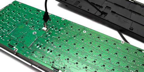 Read more: Keyboard PCB: The Design, and Factors Necessary to Build One
Introduction to Keyboard PCB Design Designing a keyboard PCB (Printed Circuit Board) is a crucial step in creating a custom mechanical keyboard. A well-designed PCB ensures the proper functioning, durability, and aesthetics of the final product. In this comprehensive article, we will delve into the intricacies of keyboard PCB design, […]
-
10 Minute Timer Circuit: Amazing Facts To Know
Posted by
–
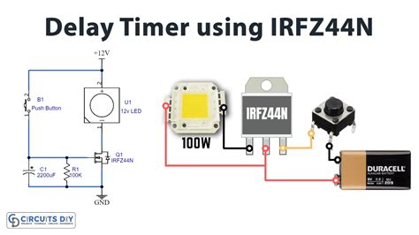 Read more: 10 Minute Timer Circuit: Amazing Facts To Know
Introduction to Timer Circuits A timer circuit is an electronic device that controls the timing of events or processes. It can be used to switch things on or off after a set period of time, or to create time delays in electronic systems. Timer circuits are found in a wide […]
-
7809 Voltage Regulator – Complete Guide
Posted by
–
 Read more: 7809 Voltage Regulator – Complete Guide
Introduction to Voltage Regulators A voltage regulator is an electronic device that maintains a constant voltage level in a circuit, even as the load current or input voltage changes. Voltage regulators are essential components in many electronic systems, from power supplies to consumer electronics, as they help ensure stable and […]


