Understanding the Properties of Rogers PCB Materials
Before delving into the design tips, it’s crucial to understand the unique properties of Rogers PCB materials. Rogers offers a range of high-frequency laminates, such as RT/duroid®, RO4000®, and RO3000® series, each with specific characteristics suitable for different applications. These materials exhibit low dielectric loss, stable dielectric constant, and excellent thermal conductivity, making them ideal for high-frequency and high-speed designs.
| Rogers Material | Dielectric Constant | Dissipation Factor | Thermal Conductivity (W/m/K) |
|---|---|---|---|
| RT/duroid® 5880 | 2.20 ± 0.02 | 0.0009 | 0.20 |
| RO4350B™ | 3.48 ± 0.05 | 0.0037 | 0.62 |
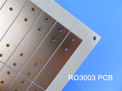
| RO3003™ | 3.00 ± 0.04 | 0.0010 | 0.50 |
Tip 1: Select the Right Rogers Material
Selecting the appropriate Rogers PCB material is the first step in designing a performance-driven board. Consider the frequency range, dielectric constant, loss tangent, and thermal requirements of your application. For example, RT/duroid® 5880 is well-suited for extremely high-frequency applications, while RO4350B™ offers a balance of performance and cost-effectiveness for high-frequency designs.
Tip 2: Optimize the Stack-up
Optimizing the PCB Stack-up is crucial for maintaining signal integrity and minimizing losses. When designing a Rogers PCB, consider the following:
- Use symmetrical stack-up to minimize warpage and ensure better manufacturability.
- Maintain consistent dielectric thickness to achieve uniform impedance throughout the board.
- Use ground planes strategically to provide shielding and reduce electromagnetic interference (EMI).
Here’s an example of a well-designed 4-layer Rogers PCB stack-up:
| Layer | Material | Thickness (mm) |
|---|---|---|
| Top | Copper | 0.035 |
| 2 | RO4350B™ | 0.254 |
| 3 | RO4450B™ (core) | 0.101 |
| Bottom | Copper | 0.035 |
Tip 3: Control Impedance
Controlling the impedance of transmission lines is essential for maintaining signal integrity and minimizing reflections. When designing Rogers PCBs, consider the following:
- Use controlled impedance traces, such as microstrip or stripline, to match the characteristic impedance of the system.
- Calculate the trace width and spacing based on the desired impedance and the dielectric properties of the Rogers material.
- Perform impedance simulations and measurements to verify the design and make necessary adjustments.
Tip 4: Minimize Losses
To achieve optimal performance, it’s important to minimize losses in Rogers PCBs. Consider the following techniques:
- Use low-loss Rogers materials with low dissipation factors to minimize dielectric losses.
- Minimize conductor losses by using wider traces and thicker copper layers, especially for high-current signals.
- Employ surface finish techniques, such as immersion silver (IAg) or electroless nickel immersion gold (ENIG), to reduce skin effect losses at high frequencies.
Tip 5: Manage Thermal Considerations
Rogers PCBs often dissipate significant amounts of heat due to high-frequency and high-power applications. Effective thermal management is crucial for maintaining performance and reliability. Consider the following:
- Use Rogers materials with high thermal conductivity to facilitate heat dissipation.
- Incorporate thermal vias and heat sinks to transfer heat away from critical components.
- Perform thermal simulations to identify hot spots and optimize the thermal design.
Tip 6: Implement Proper Grounding Techniques
Proper grounding is essential for minimizing EMI, reducing ground loops, and maintaining signal integrity in Rogers PCBs. Consider the following grounding techniques:
- Use a solid ground plane to provide a low-impedance return path for high-frequency signals.
- Implement ground stitching vias to connect ground planes on different layers and minimize ground impedance.
- Use split ground planes or moats to isolate sensitive circuits from noisy regions.
Tip 7: Optimize Layout and Routing
Optimizing the layout and routing of Rogers PCBs is crucial for achieving high performance. Consider the following tips:
- Keep critical signal traces as short as possible to minimize losses and signal distortion.
- Avoid sharp bends and discontinuities in high-frequency traces to reduce reflections and impedance mismatches.
- Maintain proper spacing between traces to minimize crosstalk and coupling.
- Use via shielding techniques, such as ground-shielded vias or coaxial vias, to reduce via-to-via coupling.
Tip 8: Perform Comprehensive Simulations and Testing
To ensure the performance and reliability of Rogers PCBs, it’s essential to perform comprehensive simulations and testing. Consider the following:
- Use electromagnetic (EM) simulation tools to analyze signal integrity, impedance matching, and EMI.
- Perform thermal simulations to identify and address potential thermal issues.
- Conduct rigorous testing, including high-frequency measurements, thermal cycling, and accelerated life testing, to validate the design and ensure long-term reliability.
Frequently Asked Questions (FAQ)
- What are the benefits of using Rogers PCB materials compared to traditional FR-4?
-
Rogers PCB materials offer superior electrical properties, such as low dielectric loss, stable dielectric constant, and excellent thermal conductivity. They are specifically designed for high-frequency and high-speed applications, providing better signal integrity and performance compared to traditional FR-4 materials.
-
Can I mix different Rogers materials in the same PCB stack-up?
-
Yes, it is possible to mix different Rogers materials in the same PCB stack-up. This is commonly done to optimize the performance and cost of the design. However, it’s important to consider the compatibility of the materials and ensure proper bonding and lamination processes.
-
How do I select the right copper thickness for my Rogers PCB design?
-
The choice of copper thickness depends on various factors, such as the desired impedance, current carrying capacity, and skin effect losses. Thicker copper layers are generally used for high-current signals and to minimize conductor losses at high frequencies. It’s recommended to consult the Rogers material datasheets and use impedance calculation tools to determine the appropriate copper thickness for your design.
-
What are some common challenges in manufacturing Rogers PCBs?
- Some common challenges in manufacturing Rogers PCBs include:
- Achieving proper bonding and lamination of Rogers materials.
- Maintaining tight tolerances for impedance control and feature sizes.
- Handling and processing thin and delicate Rogers laminates.
- Ensuring proper drill parameters and hole quality for vias and through-holes.
-
It’s important to work closely with experienced PCB manufacturers who have expertise in handling Rogers materials to mitigate these challenges.
-
How do I ensure the long-term reliability of my Rogers PCB design?
- To ensure the long-term reliability of your Rogers PCB design, consider the following:
- Perform comprehensive simulations and testing to validate the design and identify potential issues.
- Implement proper thermal management techniques to prevent overheating and thermal stress.
- Use appropriate surface finishes and coatings to protect against environmental factors and corrosion.
- Follow guidelines for handling, storage, and assembly of Rogers PCBs to minimize damage and contamination.
- Conduct regular inspections and maintenance to monitor the performance and integrity of the PCB over time.

Conclusion
Designing performance-driven Rogers PCBs requires careful consideration of various technical aspects, from material selection to layout and testing. By following the eight technical tips discussed in this article, you can optimize your Rogers PCB design for high-frequency and high-speed applications, ensuring superior signal integrity, thermal management, and overall system performance. Remember to work closely with experienced PCB manufacturers and conduct comprehensive simulations and testing to validate your design and ensure long-term reliability.


Leave a Reply