What is a 2N222 Transistor?
The 2N222 is a small-signal NPN transistor that is commonly used for low-power amplification and switching applications. It is known for its reliability, low cost, and excellent performance in a wide range of electronic projects. The 2N222 transistor is capable of handling a maximum collector current of 800mA and a maximum collector-emitter voltage of 40V, making it suitable for many general-purpose applications.
2N222 Transistor Pinouts
Pin Configuration
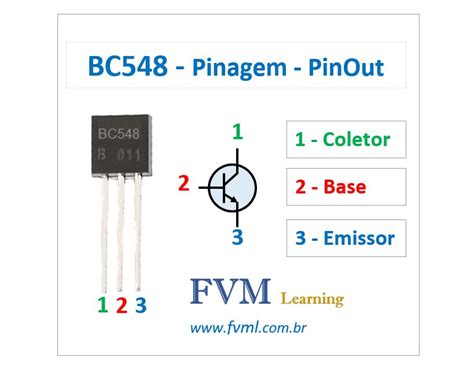
The 2N222 transistor has three pins: the emitter (E), base (B), and collector (C). The pinout configuration is as follows:
| Pin | Symbol | Description |
|---|---|---|
| 1 | E | Emitter |
| 2 | B | Base |
| 3 | C | Collector |
It is essential to identify the correct pinout of the 2N222 transistor before using it in your circuit. The pinout may vary depending on the package type, such as TO-18, TO-92, or SOT-23. Always refer to the datasheet of the specific 2N222 package you are using to ensure accurate pin identification.
Emitter (E)
The emitter is the pin that serves as the output of the transistor. In an NPN transistor like the 2N222, the emitter is connected to the negative terminal of the power supply or ground. When the transistor is in an active state, current flows from the collector to the emitter.
Base (B)
The base is the pin that controls the flow of current between the collector and emitter. By applying a small current to the base, you can regulate the larger current flowing from the collector to the emitter. The base current determines the amount of amplification or switching action performed by the transistor.
Collector (C)
The collector is the pin that acts as the input of the transistor. In an NPN transistor, the collector is connected to the positive terminal of the power supply. When the transistor is in an active state, current flows from the collector to the emitter, controlled by the base current.
Using the 2N222 Transistor
Biasing the 2N222
To properly use the 2N222 transistor, you need to bias it correctly. Biasing involves setting the appropriate voltages and currents at the base, collector, and emitter to ensure the transistor operates in the desired region (active, saturation, or cut-off).
A common biasing configuration for the 2N222 is the common-emitter amplifier. In this configuration, the emitter is connected to ground, and the base is biased with a voltage divider network. The collector is connected to the positive power supply through a load resistor.
Here’s an example of a common-emitter amplifier circuit using the 2N222:
         +Vcc
          |
          |
          R1
          |
   Vin ---+--- R2 ---+-----+
                     |     |
                     B    C|
                     |     |
                     E     R3
                     |     |
                    GND    |
                          GND
In this circuit:
– R1 and R2 form the voltage divider network that biases the base.
– R3 is the load resistor connected to the collector.
– Vin is the input signal applied to the base through the voltage divider.
– The amplified output signal is taken from the collector.
Switching Applications
Apart from amplification, the 2N222 transistor is also commonly used in switching applications. In a switching circuit, the transistor acts as an electronic switch, turning on or off based on the base current.
Here’s an example of a simple switching circuit using the 2N222:
         +Vcc
          |
          |
          R1
          |
          +---+
          |   |
   Vin ---+   |
              B
              |
              E
              |
             GND
In this circuit:
– When Vin is high (logic 1), the base-emitter junction is forward-biased, allowing current to flow from the collector to the emitter, turning the transistor on.
– When Vin is low (logic 0), the base-emitter junction is reverse-biased, preventing current flow, turning the transistor off.
– R1 is a current-limiting resistor that protects the base-emitter junction from excessive current.
Handling Precautions
When working with the 2N222 transistor, there are a few precautions to keep in mind:
-
Static Discharge: Transistors are sensitive to static electricity. Always handle them with care and use proper grounding techniques to prevent damage from electrostatic discharge (ESD).
-
Power Dissipation: Ensure that the power dissipation of the transistor does not exceed its maximum rating. Overheating can lead to permanent damage. Use appropriate heat sinks if necessary.
-
Polarity: Pay attention to the polarity of the transistor. Connecting the pins incorrectly can damage the transistor or cause the circuit to malfunction.
-
Voltage and Current Limits: Do not exceed the maximum voltage and current ratings specified in the 2N222 datasheet. Operating beyond these limits can degrade the transistor’s performance or cause permanent damage.

Frequently Asked Questions (FAQ)
-
What is the difference between a 2N222 and a 2N2222 transistor?
The 2N222 and 2N2222 are both NPN transistors, but they have slightly different specifications. The 2N2222 has a higher maximum collector current rating (800mA) compared to the 2N222 (500mA). However, for most general-purpose applications, they can be used interchangeably. -
Can I replace a 2N222 with another transistor?
Yes, you can replace a 2N222 with another NPN transistor that has similar specifications. Some compatible alternatives include the 2N2222, 2N3904, and BC547. However, always refer to the datasheets of both transistors to ensure they have comparable ratings and characteristics. -
How do I test a 2N222 transistor?
To test a 2N222 transistor, you can use a multimeter in the diode test mode. Follow these steps: - Set the multimeter to the diode test mode.
- Connect the red probe to the base and the black probe to the emitter. You should see a voltage drop of around 0.6V to 0.7V, indicating a forward-biased base-emitter junction.
- Connect the red probe to the collector and the black probe to the emitter. You should see a similar voltage drop.
-
Repeat the above steps with the probes reversed. You should see an open circuit (no voltage drop) in both cases, indicating a reverse-biased junction.
-
What is the maximum power dissipation of a 2N222 transistor?
The maximum power dissipation of a 2N222 transistor depends on the package type and the ambient temperature. For a TO-18 package at 25°C, the maximum power dissipation is typically around 500mW. However, always refer to the specific datasheet of the 2N222 package you are using for accurate power dissipation ratings. -
Can I use a 2N222 transistor for high-frequency applications?
The 2N222 transistor is primarily designed for low-frequency applications. Its transition frequency (ft) is relatively low, typically around 300 MHz. For high-frequency applications, it is recommended to use transistors specifically designed for RF or high-speed switching, such as the 2N5109 or the BFR90.
Conclusion
Understanding the 2N222 transistor pinouts is essential for successfully incorporating it into your electronic projects. By properly identifying the emitter, base, and collector pins and biasing the transistor correctly, you can leverage its amplification and switching capabilities effectively.
Remember to handle the 2N222 transistor with care, adhere to its maximum ratings, and follow proper handling precautions to ensure reliable operation and longevity.
With this comprehensive guide, you should now have a solid understanding of the 2N222 transistor pinouts and how to utilize them in your circuits. Happy building!


Leave a Reply