Introduction to Flexible PCBs for Satellites
Flexible printed circuit boards, or flex PCBs, have emerged as the go-to choice for many demanding electronics applications that require durability, reliability, and the ability to fit into tight, compact spaces. One of the most challenging yet crucial applications where flex PCBs shine is in satellites and spacecraft.
The unforgiving environment of space, with extreme temperatures, radiation, vibration, and the need for absolute minimum size and weight, requires specialized electronics that can withstand these harsh conditions. Flexible PCBs have proven to be up to the task, offering numerous advantages over traditional rigid PCBs for satellite applications.
In this comprehensive article, we’ll dive deep into the world of flex PCBs and explore the key reasons why they have become the preferred choice for satellite electronics. We’ll cover the unique properties and benefits of flex PCBs, the challenges of designing for space, and real-world examples of successful flex PCB implementations in satellite missions.
The Unique Properties of Flexible PCBs
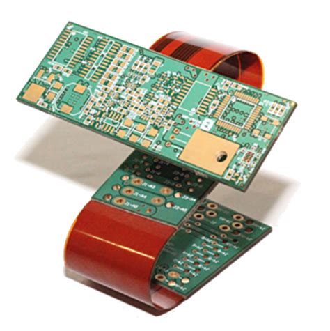
Flexible PCBs are characterized by their thin, lightweight, and bendable construction. Unlike rigid PCBs made from fiberglass, flex PCBs are fabricated using thin, flexible plastic substrates such as polyimide (Kapton) or polyester. Conductive copper traces are laminated onto these substrates to create the circuit pattern.
The key properties that make flex PCBs ideal for satellites include:
Lightweight and Thin Profile
Every gram counts when launching payloads into space. Flex PCBs are significantly thinner and lighter compared to rigid boards, allowing satellite designers to minimize the overall mass of the spacecraft. This weight reduction translates to fuel savings and increased payload capacity.
| Property | Rigid PCB | Flex PCB |
|---|---|---|
| Thickness | 1.6 mm | 0.2 mm |
| Weight (10×10 cm) | 12 g | 2 g |
As the table illustrates, a typical flex PCB can be up to 80% thinner and over 80% lighter than an equivalent rigid board. When multiplied across the numerous PCBs in a satellite, the weight savings become substantial.
Flexibility and Conformity
The ability of flex PCBs to bend, fold, and conform to complex shapes is a game-changer for satellite packaging. Rigid PCBs are limited to flat, two-dimensional layouts, wasting valuable space. Flex PCBs can be designed to fit into tight, irregular spaces, wrapping around components and conforming to the satellite’s structure.
This flexibility allows for more efficient use of the limited real estate inside a satellite, enabling denser packaging and miniaturization. It also reduces the need for bulky connectors and cables, as flex PCBs can directly interconnect components.
Vibration and Shock Resistance
Satellites endure intense vibration during launch and must withstand the constant bombardment of micrometeorites and space debris. The flexible nature of flex PCBs makes them inherently resistant to vibration and shock.
Unlike rigid PCBs which can crack under stress, flex PCBs can absorb and dissipate mechanical energy, minimizing the risk of failure. The lack of rigid interconnects also reduces the chances of solder joint fractures, a common failure mode in harsh environments.
Thermal Management
Satellites experience extreme temperature fluctuations, from the cold of space to the heat generated by electronic components. Flex PCBs offer better thermal management compared to rigid boards due to their thin profile and direct contact with components.
The polyimide substrate used in flex PCBs has a lower coefficient of thermal expansion (CTE) compared to FR-4, the standard material for rigid PCBs. This means flex PCBs are less prone to thermal stresses and warping, enhancing reliability.
| Material | CTE (ppm/°C) |
|---|---|
| Polyimide | 20 |
| FR-4 | 70 |
The table highlights the significant difference in CTE between polyimide and FR-4. The lower CTE of polyimide makes flex PCBs more dimensionally stable across temperature ranges.
High-Density Interconnects
Flex PCBs enable higher-density interconnects compared to rigid boards. The thin substrates and fine-pitch copper traces allow for smaller vias, tighter spacing, and more layers in a given thickness.
This high-density capability is crucial for satellite electronics, where space is at a premium. Flex PCBs can pack more functionality into a smaller footprint, reducing the overall size and weight of the satellite.

Challenges of Designing Flex PCBs for Space
Designing flex PCBs for satellite applications comes with its own set of challenges. The harsh space environment and stringent reliability requirements demand careful consideration and specialized design techniques.
Material Selection
Choosing the right materials is critical for space-grade flex PCBs. The substrate, copper, and any additional layers must withstand the rigors of space, including:
- Wide temperature range (-150°C to +150°C)
- Vacuum conditions
- Radiation exposure
- Atomic oxygen erosion
Polyimide (Kapton) is the most common substrate material for space-grade flex PCBs due to its excellent thermal stability, radiation resistance, and mechanical properties. For the conductive layers, high-purity copper with enhanced adhesion to the substrate is used.
Controlled Impedance
Many satellite applications, such as high-speed data transmission and RF circuits, require controlled impedance traces. Designing controlled impedance on flex PCBs is more challenging compared to rigid boards due to the thinner substrates and varying dielectric constants.
Accurate modeling and simulation are essential to ensure the desired impedance is achieved. Techniques such as differential signaling and ground planes can help maintain signal integrity on flex PCBs.
Stiffeners and Strain Relief
Although flexibility is a key advantage of flex PCBs, it can also lead to issues if not properly managed. Repeated flexing can cause copper traces to crack or delaminate, leading to failures.
To mitigate this risk, stiffeners are often used in areas where the flex PCB is mounted or interfaces with connectors. Stiffeners provide local reinforcement and prevent excessive bending. Strain relief features, such as curves and service loops, are also incorporated into the design to distribute stress evenly.
Shielding and Grounding
Satellites are exposed to various sources of electromagnetic interference (EMI), both from internal components and the space environment. Proper shielding and grounding are essential to ensure the integrity of sensitive signals.
Flex PCBs can incorporate shielding layers, such as copper planes or conductive fabrics, to provide EMI protection. Careful attention must be paid to the grounding scheme, ensuring a low-impedance path for return currents and avoiding ground loops.
Testing and Qualification
Space-grade flex PCBs undergo rigorous testing and qualification to ensure they can withstand the harsh conditions of space. This includes:
- Thermal cycling
- Vibration and shock testing
- Outgassing tests
- Radiation exposure
- Functional and electrical testing
Specialized test fixtures and procedures are developed to simulate the space environment and verify the performance of the flex PCBs. Qualification testing is often performed at the component, board, and system levels to ensure reliability.

Real-World Examples of Flex PCBs in Satellites
Flex PCBs have been successfully used in numerous satellite missions, demonstrating their reliability and performance in space. Here are a few notable examples:
CubeSats
CubeSats are miniaturized satellites built in standard units of 10 cm cubes. These small satellites have revolutionized space exploration by providing low-cost access to space for research, education, and technology demonstration.
Flex PCBs are a key enabling technology for CubeSats, allowing them to pack a lot of functionality into a tiny form factor. The flexibility of flex PCBs allows them to be folded and stacked, maximizing the use of the limited internal volume.
Mars Rovers
NASA’s Mars rovers, such as Curiosity and Perseverance, rely on flex PCBs for their complex electronics systems. The rovers’ mobility systems, cameras, and scientific instruments all utilize flex PCBs for their compact packaging and reliability.
The flexible interconnects allow the rovers to accommodate the tight spaces and complex geometries of their structures. Flex PCBs also provide the durability needed to withstand the harsh Martian environment, including extreme temperature swings and dust storms.
Satellite Antennas
Satellite antennas, particularly deployable antennas, make extensive use of flex PCBs. The thin, lightweight nature of flex PCBs allows them to be integrated into the antenna structure, providing the necessary interconnects for the radiating elements.
Flex PCBs enable the design of complex, high-performance antennas that can be stowed compactly during launch and deployed once in orbit. This includes phased array antennas, reflectarrays, and inflatable antennas.

FAQs
Q1: Can flex PCBs withstand the radiation levels in space?
A1: Yes, flex PCBs made with appropriate materials, such as polyimide substrates and high-purity copper, can withstand the radiation levels encountered in space. The thin profile of flex PCBs also helps minimize the radiation cross-section.
Q2: How do flex PCBs handle the thermal challenges of space?
A2: Flex PCBs offer better thermal management compared to rigid boards due to their thin profile and direct contact with components. The polyimide substrate used in flex PCBs has a low coefficient of thermal expansion, making them less prone to thermal stresses and warping.
Q3: Are flex PCBs more expensive than rigid PCBs for satellite applications?
A3: While flex PCBs may have a higher initial cost compared to rigid PCBs, they offer significant savings in terms of space, weight, and reliability. The benefits of flex PCBs often outweigh the cost premium for satellite applications.
Q4: How are flex PCBs tested and qualified for space use?
A4: Space-grade flex PCBs undergo rigorous testing and qualification, including thermal cycling, vibration and shock testing, outgassing tests, radiation exposure, and functional and electrical testing. Specialized test fixtures and procedures are used to simulate the space environment and verify performance.
Q5: Can flex PCBs be used for high-speed data transmission in satellites?
A5: Yes, flex PCBs can be designed for high-speed data transmission in satellites. Techniques such as controlled impedance, differential signaling, and ground planes are used to maintain signal integrity on flex PCBs. Careful design and simulation are required to ensure the desired performance is achieved.
Conclusion
Flexible PCBs have emerged as the preferred choice for satellite applications due to their unique properties and benefits. Their lightweight, thin profile, flexibility, and durability make them ideally suited for the harsh environment of space.
The ability of flex PCBs to conform to complex shapes, provide high-density interconnects, and offer excellent thermal management has revolutionized satellite electronics packaging. They have enabled the miniaturization of satellites, such as CubeSats, and have proven their reliability in critical missions like Mars rovers.
Designing flex PCBs for space comes with its own set of challenges, including material selection, controlled impedance, strain relief, shielding, and qualification testing. However, with careful design and specialized techniques, flex PCBs have demonstrated their ability to meet the stringent requirements of satellite applications.
As the demand for smaller, more capable satellites continues to grow, flexible PCBs will undoubtedly play a crucial role in enabling the next generation of space missions. Their versatility, reliability, and performance make them the go-to choice for pushing the boundaries of satellite electronics.


Leave a Reply