Introduction to Trimpot Pinout
A trimpot, short for trimming potentiometer, is a small variable resistor used for fine-tuning and calibration in electronic circuits. Understanding the trimpot pinout is essential for properly integrating these components into your projects. In this comprehensive article, we will explore the features, uses, and configuration of trimpot pinouts, providing you with the knowledge needed to effectively utilize these versatile components.
What is a Trimpot?
A trimpot is a miniature potentiometer designed for precise adjustments in electronic circuits. Unlike regular potentiometers, which are typically larger and have a rotary knob for manual adjustment, trimpots are compact and are adjusted using a small screwdriver. They are commonly used for fine-tuning and calibration purposes, allowing engineers and hobbyists to set specific resistance values or voltage levels in their circuits.
Key Features of Trimpots
- Compact Size: Trimpots are significantly smaller than regular potentiometers, making them ideal for space-constrained applications.
- Precise Adjustment: With their small form factor, trimpots offer precise and fine-grained control over resistance values.
- Stable Performance: Trimpots are designed to maintain their set resistance value over time, ensuring reliable operation in critical applications.
- Wide Resistance Range: Trimpots are available in a wide range of resistance values, typically ranging from a few ohms to several megaohms.

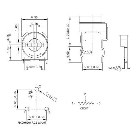
Trimpot Pinout Configuration
To effectively use trimpots in your projects, it’s crucial to understand their pinout configuration. Most trimpots have three pins, each serving a specific purpose. Let’s take a closer look at the standard trimpot pinout.
Standard Trimpot Pinout
| Pin | Function |
|---|---|
| 1 | Counterclockwise (CCW) Terminal |
| 2 | Wiper (Adjustable Terminal) |
| 3 | Clockwise (CW) Terminal |
- Pin 1 (CCW Terminal): This pin is connected to one end of the resistive element inside the trimpot. It represents the minimum resistance value when the wiper is fully turned counterclockwise.
- Pin 2 (Wiper): The wiper pin is the adjustable terminal that slides along the resistive element. Its position determines the resistance value between the CCW and CW terminals.
- Pin 3 (CW Terminal): Connected to the other end of the resistive element, this pin represents the maximum resistance value when the wiper is fully turned clockwise.
By adjusting the position of the wiper using a small screwdriver, you can vary the resistance between the CCW and CW terminals, effectively controlling the voltage or current in your circuit.
Trimpot Schematic Symbol
In electronic schematics, trimpots are represented by a specific symbol that clearly illustrates their functionality. The schematic symbol for a trimpot typically looks like this:
      ┌───────┐
      │       │
   ───┤   ╲   ├───
      │   ╱   │
      └───────┘
        ▲
        │
        └─ Wiper (Adjustable Terminal)
The arrow pointing to the wiper terminal indicates that it is the adjustable contact that moves along the resistive element.

Trimpot Resistance Range and Taper
Trimpots are available in a wide range of resistance values to suit various application requirements. Common resistance ranges include:
- 100 ohms to 1 megohm
- 500 ohms to 5 megohms
- 1 kiloohm to 10 megohms
When selecting a trimpot for your project, consider the desired resistance range and the level of precision required for your application.
In addition to the resistance range, trimpots also come in different tapers. The taper refers to the relationship between the wiper position and the resistance value. The two most common trimpot tapers are:
- Linear Taper: In a linear taper trimpot, the resistance varies linearly with the wiper position. This means that the resistance change is directly proportional to the wiper movement.
- Logarithmic Taper: Logarithmic taper trimpots have a non-linear relationship between the wiper position and the resistance value. The resistance change is logarithmic, allowing for finer control at one end of the range and coarser control at the other end.
Choose the appropriate taper based on your specific application requirements and the desired control characteristics.

Trimpot Mounting and Packaging
Trimpots are available in various mounting and packaging options to suit different PCB layouts and assembly methods. Some common mounting styles include:
- Through-Hole: Through-hole trimpots have long pins that are inserted into holes drilled in the PCB and soldered in place. They offer a secure and reliable connection.
- Surface Mount (SMD): Surface mount trimpots are designed for automated assembly processes. They have small pads that are soldered directly onto the surface of the PCB, resulting in a more compact and low-profile installation.
When selecting a trimpot, consider the mounting style that best fits your PCB design and manufacturing process.
Applications of Trimpots
Trimpots find applications in a wide range of electronic circuits and systems. Some common uses include:
- Calibration: Trimpots are extensively used for calibrating sensors, instruments, and other electronic devices. By adjusting the trimpot, you can fine-tune the output or sensitivity of the device to achieve accurate and reliable measurements.
- Voltage and Current Adjustment: Trimpots can be used to set reference voltages or limit current in power supply circuits. By varying the resistance, you can control the output voltage or current to meet specific requirements.
- Gain Control: In amplifier circuits, trimpots are used to adjust the gain or amplification factor. This allows you to optimize the signal level and prevent clipping or distortion.
- Threshold Setting: Trimpots are employed in comparator circuits to set the threshold voltage at which the comparator triggers. By adjusting the trimpot, you can fine-tune the switching point according to your application needs.
- Frequency Tuning: In oscillator circuits, trimpots are used to adjust the frequency of the generated signal. By varying the resistance, you can fine-tune the oscillation frequency to match a specific value or compensate for component tolerances.
These are just a few examples of the many applications where trimpots prove invaluable. Their precision, stability, and adjustability make them essential components in a wide range of electronic projects.
Trimpot Selection Considerations
When selecting a trimpot for your project, there are several key factors to consider:
- Resistance Range: Choose a trimpot with a resistance range that covers the desired values for your application. Consider the minimum and maximum resistance needed and select a trimpot accordingly.
- Power Rating: Determine the maximum power dissipation required for your circuit and choose a trimpot with an appropriate power rating. Exceeding the power rating can lead to component failure and potential damage to your circuit.
- Tolerance: Trimpots are available with different tolerance ratings, indicating the accuracy of the resistance value. Select a trimpot with a tolerance that meets your application’s precision requirements.
- Taper: As discussed earlier, trimpots come in linear and logarithmic tapers. Consider the desired control characteristics and choose the appropriate taper for your application.
- Mounting Style: Decide whether you need a through-hole or surface mount trimpot based on your PCB design and assembly process. Ensure compatibility with your PCB layout and manufacturing capabilities.
- Environmental Factors: Consider the operating environment of your circuit and select a trimpot that can withstand the expected temperature range, humidity, and other environmental conditions.
- Adjustment Method: Trimpots can be adjusted using a screwdriver or a built-in knob. Choose the adjustment method that suits your application and user requirements.
By carefully considering these factors, you can select the most suitable trimpot for your project, ensuring optimal performance and reliability.
Trimpot Configuration and Adjustment
Once you have selected the appropriate trimpot for your application, it’s time to configure and adjust it in your circuit. Here are the steps to follow:
- Identify the Pinout: Refer to the trimpot’s datasheet or pinout diagram to identify the CCW, wiper, and CW terminals. Ensure that you have the correct orientation when connecting the trimpot to your circuit.
- Connect the Trimpot: Solder the trimpot’s pins to the appropriate pads or through-holes on your PCB. Double-check the connections to avoid any shorts or open circuits.
- Set the Initial Resistance: Before powering on your circuit, set the trimpot to its mid-range position or the desired initial resistance value. This can be done by gently turning the adjustment screw or knob with a suitable screwdriver.
- Power On and Test: Apply power to your circuit and verify that it is functioning as expected. Use a multimeter to measure the resistance between the wiper and the CCW or CW terminal to confirm the initial resistance setting.
- Fine-Tune the Resistance: With your circuit powered on, carefully adjust the trimpot using the screwdriver or knob until you achieve the desired output or performance. Monitor the relevant parameters (e.g., voltage, current, frequency) while making adjustments to ensure accurate calibration.
- Secure the Adjustment: Once you have reached the optimal setting, you may want to secure the trimpot’s adjustment screw or knob to prevent accidental changes. Some trimpots have a locking mechanism or can be sealed with a drop of glue to maintain the setting.
Remember to handle trimpots with care during the adjustment process. Applying excessive force or turning the adjustment screw beyond its limits can damage the component and affect its performance.
Trimpot Maintenance and Troubleshooting
To ensure the longevity and reliable operation of trimpots in your circuits, proper maintenance and troubleshooting practices are essential. Here are some tips to keep in mind:
- Cleanliness: Keep the trimpot and the surrounding area clean and free from dust, dirt, and debris. Contaminants can interfere with the smooth movement of the wiper and cause erratic behavior or premature failure.
- Gentle Handling: When adjusting trimpots, use a suitable screwdriver and apply gentle pressure. Avoid excessive force or sudden movements that can damage the internal components or cause the wiper to lose contact with the resistive element.
- Periodic Calibration: Over time, trimpots may drift from their set values due to environmental factors or mechanical wear. Perform periodic calibration checks and readjust the trimpots as necessary to maintain accurate performance.
- Visual Inspection: Regularly inspect the trimpot for any signs of physical damage, such as cracks, bent pins, or loose connections. Address any issues promptly to prevent further damage or malfunction.
- Troubleshooting: If you encounter problems with your trimpot-based circuit, start by verifying the connections and ensuring that the trimpot is properly seated. Use a multimeter to measure the resistance values and check for any shorts or open circuits. If the issue persists, consider replacing the trimpot with a new one.
By following these maintenance and troubleshooting practices, you can extend the lifespan of your trimpots and ensure reliable operation in your electronic projects.
Frequently Asked Questions (FAQ)
-
What is the difference between a trimpot and a regular potentiometer?
A: Trimpots are miniature potentiometers designed for precise adjustments and calibration. They are smaller in size and are typically adjusted using a screwdriver, whereas regular potentiometers are larger and have a rotary knob for manual adjustment. -
Can I use a trimpot as a variable resistor in my circuit?
A: Yes, trimpots can be used as variable resistors in circuits where precise resistance adjustment is required. By connecting the wiper and one of the end terminals (CCW or CW), you can vary the resistance value within the trimpot’s range. -
How do I know which taper to choose for my trimpot?
A: The choice of taper depends on your application requirements. Linear taper trimpots provide a proportional resistance change with wiper movement, while logarithmic taper trimpots offer finer control at one end and coarser control at the other end. Consider the desired control characteristics and select the appropriate taper accordingly. -
Are trimpots polarized components?
A: No, trimpots are not polarized components. They can be connected in either direction in a circuit without affecting their functionality. However, it’s important to identify the correct pinout and connect the terminals accurately. -
Can I replace a trimpot with a fixed resistor?
A: In some cases, you can replace a trimpot with a fixed resistor of the desired value. However, this eliminates the adjustability and calibration capabilities provided by the trimpot. If your application requires fine-tuning or the ability to compensate for component variations, using a trimpot is recommended.
Conclusion
Trimpots are versatile and essential components in electronic circuits, offering precise adjustability and calibration capabilities. By understanding the trimpot pinout, features, and configuration, you can effectively integrate these miniature potentiometers into your projects. Whether you’re designing sensor interfaces, power supplies, amplifiers, or oscillators, trimpots provide the flexibility and control needed to achieve optimal performance.
When selecting trimpots, consider factors such as resistance range, power rating, tolerance, taper, mounting style, and environmental requirements. Proper configuration and adjustment procedures ensure accurate and reliable operation. Regular maintenance and troubleshooting practices help maintain the longevity and functionality of your trimpot-based circuits.
By mastering the concepts and techniques presented in this comprehensive article, you’ll be well-equipped to leverage the power of trimpots in your electronic designs. Experiment, innovate, and unlock new possibilities with these tiny yet mighty components. Happy tinkering!


Leave a Reply