Introduction to Solder-joint Classification
Soldering is a critical process in the assembly of printed circuit boards (PCBs) and electronic components. The quality and reliability of solder joints directly impact the performance and longevity of electronic devices. In this article, we will focus on the classification of soldered through-hole pads, a common type of solder joint used in PCB assembly.
What are Through-hole Pads?
Through-hole pads, also known as plated through-holes (PTHs), are conductive pads that connect the top and bottom layers of a PCB. These pads have a hole drilled through them, allowing component leads or wires to be inserted and soldered in place. Through-hole pads provide a strong mechanical connection and are often used for components that require higher reliability or are subject to mechanical stress.
Importance of Solder-joint Classification
Classifying solder joints is essential for quality control and assurance in PCB manufacturing. By categorizing solder joints based on their appearance and characteristics, manufacturers can identify defects, assess the overall quality of the soldering process, and take corrective actions if necessary. Solder-joint classification helps ensure that the assembled PCBs meet the required standards and specifications.
Visual Inspection Criteria for Solder-joint Classification
Visual inspection is the primary method used to classify solder joints. Inspectors examine the solder joints under magnification to assess their quality based on various criteria. The following table outlines the key visual inspection criteria for classifying soldered through-hole pads:
| Criteria | Description |
|---|---|
| Wetting | The degree to which the solder flows and adheres to the pad and component lead. Good wetting ensures a strong and reliable connection. |
| Fillets | The concave shape formed by the solder between the pad and the component lead. Properly formed fillets indicate good solder flow and joint strength. |
| Solder coverage | The extent to which the solder covers the pad and the component lead. Adequate solder coverage is essential for electrical conductivity and mechanical stability. |
| Solder volume | The amount of solder used in the joint. Insufficient or excessive solder can lead to weak or bulky joints, respectively. |
| Voids | Gaps or air pockets within the solder joint. Voids can reduce the strength and conductivity of the joint. |
| Contamination | The presence of foreign materials, such as flux residue or dirt, on the solder joint. Contamination can affect the joint’s integrity and reliability. |
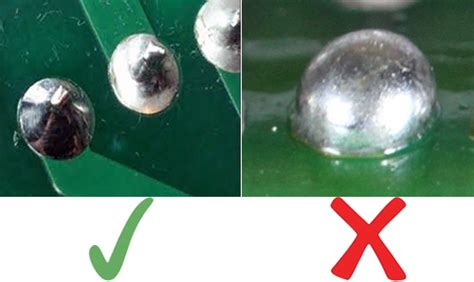
Wetting
Wetting refers to the ability of molten solder to flow and adhere to the surfaces of the pad and component lead. Good wetting is characterized by a smooth, shiny, and uniform appearance of the solder joint. Poor wetting, on the other hand, may result in a dull, rough, or incomplete solder joint.
Fillets
Fillets are the concave shapes formed by the solder between the pad and the component lead. A well-formed fillet should have a smooth, concave profile and should extend up the lead and onto the pad. Insufficient or excessive fillets may indicate problems with solder volume or wetting.
Solder Coverage
Solder coverage refers to the extent to which the solder covers the pad and the component lead. Adequate solder coverage ensures good electrical conductivity and mechanical stability. Insufficient coverage may lead to weak or intermittent connections, while excessive coverage can cause short circuits or impede the insertion of the component lead.
Solder Volume
Solder volume is the amount of solder used in the joint. The ideal solder volume should be sufficient to form proper fillets and provide adequate coverage without being excessive. Insufficient solder volume may result in weak joints, while excessive volume can lead to bulky or bridged joints.
Voids
Voids are gaps or air pockets within the solder joint. They can occur due to improper soldering techniques, contamination, or outgassing of the flux. Voids reduce the strength and conductivity of the joint and can lead to reliability issues over time.
Contamination
Contamination refers to the presence of foreign materials, such as flux residue, dirt, or oxidation, on the solder joint. Contaminants can interfere with the proper formation of the solder joint and affect its long-term reliability. Proper cleaning and handling procedures should be followed to minimize contamination.

Solder-joint Classification Standards
Several industry standards provide guidelines and criteria for classifying solder joints. These standards ensure consistency and reliability in the evaluation process. The following table lists some of the commonly used solder-joint classification standards:
| Standard | Description |
|---|---|
| IPC-A-610 | The most widely recognized standard for solder-joint acceptance criteria in the electronics industry. It provides detailed visual inspection criteria for various types of solder joints, including through-hole pads. |
| IPC J-STD-001 | A standard that defines the requirements for soldered electrical and electronic assemblies. It includes guidelines for materials, methods, and verification criteria. |
| MIL-STD-2000 | A military standard that establishes requirements for soldered electrical and electronic assemblies. It focuses on high-reliability applications and includes stringent acceptance criteria. |
These standards provide a framework for evaluating solder joints and ensuring that they meet the required quality and reliability levels. Manufacturers and inspectors should be familiar with the relevant standards and apply them consistently during the classification process.

Solder-joint Defect Categories
During the visual inspection process, solder joints that do not meet the acceptance criteria are classified as defects. The following table lists some common solder-joint defect categories for through-hole pads:
| Defect Category | Description |
|---|---|
| Insufficient solder | The solder volume is inadequate, resulting in incomplete coverage or weak fillets. |
| Excessive solder | The solder volume is excessive, causing bulky or bridged joints. |
| Poor wetting | The solder does not flow or adhere properly to the pad or component lead, resulting in a dull or rough appearance. |
| Voids | Gaps or air pockets are present within the solder joint. |
| Contamination | Foreign materials, such as flux residue or dirt, are present on the solder joint. |
| Cracked joint | The solder joint has cracks or fissures, indicating mechanical stress or thermal cycling issues. |
| Cold joint | The solder joint has a dull, grainy appearance due to insufficient heat during the soldering process. |
Identifying and categorizing defects helps manufacturers take corrective actions and improve the soldering process. By addressing the root causes of defects, such as improper soldering techniques, inadequate cleaning, or incorrect component placement, manufacturers can enhance the overall quality and reliability of the assembled PCBs.

Automated Solder-joint Inspection
While visual inspection is the primary method for classifying solder joints, automated inspection systems have gained popularity in recent years. These systems use advanced imaging techniques, such as machine vision and X-ray inspection, to detect and classify solder-joint defects.
Machine Vision Inspection
Machine vision systems use high-resolution cameras and image processing algorithms to analyze solder joints. These systems can quickly scan the PCB and compare the solder joints against predefined criteria. Machine vision inspection offers several advantages:
- High-speed inspection: Machine vision systems can inspect hundreds or thousands of solder joints per minute, significantly reducing the inspection time compared to manual methods.
- Consistency: Automated inspection eliminates the subjectivity and variability associated with human visual inspection, ensuring consistent classification results.
- Traceability: Machine vision systems can store and analyze inspection data, allowing for traceability and statistical process control.
X-ray Inspection
X-ray inspection systems use penetrating radiation to generate images of the internal structure of solder joints. This technique is particularly useful for inspecting hidden or obscured solder joints, such as those under components or in multi-layer PCBs. X-ray inspection can detect defects such as voids, cracks, and insufficient solder penetration.
Automated inspection systems complement visual inspection by providing objective and quantitative data on solder-joint quality. However, visual inspection remains essential for validating the automated results and addressing complex or ambiguous cases.
Frequently Asked Questions (FAQ)
-
Q: What is the purpose of solder-joint classification?
A: Solder-joint classification helps assess the quality and reliability of soldered connections in PCB assembly. By categorizing solder joints based on their appearance and characteristics, manufacturers can identify defects, ensure compliance with industry standards, and take corrective actions to improve the soldering process. -
Q: What are the main visual inspection criteria for classifying solder joints?
A: The main visual inspection criteria include wetting, fillets, solder coverage, solder volume, voids, and contamination. Inspectors examine these characteristics to determine the quality and acceptability of the solder joints. -
Q: What are some common solder-joint defect categories?
A: Common solder-joint defect categories include insufficient solder, excessive solder, poor wetting, voids, contamination, cracked joints, and cold joints. These defects can affect the electrical and mechanical integrity of the solder joints and should be identified and addressed during the inspection process. -
Q: What are the advantages of automated solder-joint inspection?
A: Automated solder-joint inspection, such as machine vision and X-ray inspection, offers advantages such as high-speed inspection, consistency, and traceability. These systems can quickly scan and analyze solder joints, providing objective and quantitative data on their quality. -
Q: Can automated inspection replace visual inspection entirely?
A: While automated inspection systems offer many benefits, they should be used in conjunction with visual inspection. Visual inspection remains essential for validating automated results, addressing complex cases, and ensuring the overall quality of the soldering process.
Conclusion
Solder-joint classification is a critical aspect of quality control in PCB assembly. By visually inspecting soldered through-hole pads and categorizing them based on industry standards, manufacturers can ensure the reliability and performance of electronic devices. Visual inspection criteria, such as wetting, fillets, solder coverage, and contamination, provide a framework for assessing solder-joint quality.
Automated inspection systems, including machine vision and X-ray inspection, have emerged as valuable tools for high-speed and consistent solder-joint classification. However, visual inspection remains crucial for validating automated results and addressing complex cases.
By understanding and applying solder-joint classification standards, identifying defect categories, and utilizing a combination of visual and automated inspection techniques, manufacturers can enhance the quality and reliability of their soldered through-hole assemblies.


Leave a Reply