Introduction to Start-Stop Circuits
Start-stop circuits are a fundamental component in many electrical and control systems. They allow operators to easily start and stop equipment like motors, pumps, conveyors and more with the push of a button. Start-stop circuits provide a safe and reliable way to control machinery.
In this comprehensive guide, we’ll cover everything you need to know about start-stop circuits including:
– The basic components and operation of a start-stop circuit
– Different types of start-stop circuits
– Applications and examples of where they are used
– Designing and troubleshooting tips
– Frequently asked questions about start-stop circuits
By the end, you’ll have a solid understanding of these important control circuits and how they are applied in industrial settings. Let’s dive in!
How Start-Stop Circuits Work
Basic Components and Operation
At its core, a start-stop circuit allows an operator to start and stop a piece of equipment remotely and safely. It consists of:
- A normally open START pushbutton
- A normally closed STOP pushbutton
- A main contactor to supply power to the load
- An auxiliary contactor to seal in the circuit
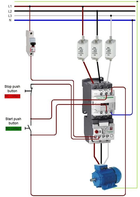
Here’s a simple start-stop circuit diagram:
When the START button is pressed momentarily, it energizes the main contactor coil (M). The M contactor closes, supplying power to the load (motor, pump, etc.). At the same time, the auxiliary contactor (Ma) also closes. This seals in the circuit, keeping the M contactor energized even when the START button is released.
Pressing the STOP button breaks the seal-in circuit and de-energizes the M contactor coil, thus removing power from the load. The circuit remains off until the START button is pressed again.
Some advantages of start-stop circuits include:
– Allow remote control of equipment
– Permit hands-free operation once started
– Provide low-voltage control of higher voltage loads
– Enable safety interlocking with other circuits
Momentary vs Maintained Contacts
Start-stop circuits can be designed using either momentary or maintained contacts for the START and STOP buttons.
With momentary contacts, the pushbuttons return to their normal state (open or closed) when released. Momentary is more common, as the operator just needs to tap the START or STOP button.
Maintained contacts remain in the activated state when pressed. The operator would have to pull the button back out to release it. This is less common but sometimes used for safety functions that should be more intentional.
3-Wire vs 2-Wire Control
You’ll often hear start-stop circuits referred to as either 3-wire or 2-wire control. This refers to the number of wires or conductors needed between the START/STOP station and the control panel.
A 3-wire circuit, like the one shown earlier, uses two momentary pushbuttons and requires a separate wire for START, STOP, and common. This provides the seal-in function.
In a 2-wire circuit, a single maintained switch is used, and the START and STOP functions share a common conductor. While simpler to wire, 2-wire circuits are more prone to safety issues if a wire breaks.
For most applications, 3-wire start-stop circuits are preferred due to their safer operation and use of momentary buttons. However, 2-wire is still used for certain basic functions.

Types of Start-Stop Circuits
Now that we’ve covered the basics, let’s look at some common variations and enhancements to the standard start-stop circuit.
Multiple Start-Stop Stations
In larger systems, it’s often necessary to control a load from more than one location. For example, you may need START/STOP buttons at each end of a long conveyor.
To accomplish this, multiple START buttons are wired in parallel so that any one of them can start the circuit. Multiple STOP buttons are wired in series so that any one of them can stop the circuit.
Jogging Circuit
A jogging circuit allows the operator to briefly “bump” or “inch” the motor to align a shaft or slowly advance a conveyor. It uses a separate normally open pushbutton wired directly to the motor starter.
Pressing and holding the JOG button runs the motor only as long as the button is held. Releasing the button immediately stops the motor.
Jog circuits also require a normally closed contact from the main contactor wired in series with the JOG button. This prevents jogging while the motor is already running.
Reversing Circuit
Some applications require the ability to run a motor in both forward and reverse directions. A reversing start-stop circuit can accomplish this using two separate contactors.
The FWD and REV contactors are electrically interlocked so that both cannot be energized simultaneously, which would cause a phase-to-phase short circuit. Their START buttons are also interlocked so that the direction cannot be instantly reversed without stopping first.
Limit Switch Control
Start-stop circuits are frequently integrated with limit switches that automatically stop a motion when a certain position is reached. The limit switch is wired as a normally closed contact in series with the STOP button.
When the limit switch is triggered, it opens the circuit just like pressing the STOP button. Limit switches are commonly used in applications like elevators, door operators, and machine tools.

Applications and Examples
Start-stop circuits are used extensively throughout industry, infrastructure, and buildings. Some common applications include:
Motor Control
The most prevalent use of start-stop circuits is for controlling motors. From small fans and pumps up to large compressors and hoists, start-stop circuits allow safe and convenient control of electric motors.
Conveyor Control
Start-stop stations are used to control individual conveyor sections as well as entire conveyor lines. They allow operators to quickly halt the conveyor if a problem occurs.
Door and Gate Operators
Electrically operated doors and gates in factories, garages, and secure areas use start-stop circuits for open and close functions. Limit switches are incorporated to stop the door in the fully open and fully closed positions.
Pump Control
Start-stop circuits allow manual control of pumps in industrial processes, water treatment plants, and irrigation systems. They are also integrated with level switches for automatic filling and emptying of tanks.
Machine Tools
Almost all machine tools like drills, mills, lathes, and grinders use start-stop circuits for their spindle motors, coolant pumps, and lubricators. They allow the operator to easily start and stop the machine while keeping hands free for material handling.

Design and Troubleshooting Tips
When designing and troubleshooting start-stop circuits, here are some key tips to keep in mind:
Use Proper Wiring Practices
Make sure all wires and terminals are properly labeled. Use a multi-conductor cable between the START/STOP station and panel to minimize wiring errors. Include disconnecting means and overcurrent protection as needed.
Ensure Fail-Safe Operation
In a 3-wire circuit, the STOP button should be hardwired to the control circuit. This ensures the circuit can always be stopped even if the START button or wiring fails.
Perform Risk Assessments
Make sure the start-stop circuit is appropriate for the level of risk in the application. For higher risk situations, consider using redundant circuits, emergency stop buttons, or safety relays.
Test and Verify Operation
Always fully test the circuit after installation and any modifications. Verify that the START and STOP buttons operate the load correctly from all stations. Check that any interlocks, permissives, or limit switches function properly.
Use Pilot Lights for Feedback
Including pilot lights in your start-stop circuit gives the operator visual confirmation of the circuit status. Use a green light to show when the circuit is running and a red light to indicate a stopped or faulted condition.
Frequently Asked Questions
What is the difference between a start-stop circuit and an on-off switch?
An on-off switch directly makes and breaks the power to the load. A start-stop circuit uses low-voltage control elements to switch a higher voltage/current load indirectly. Start-stop circuits also allow remote control from multiple locations.
Can you use a start-stop circuit with a light or other non-motor load?
Yes, start-stop circuits can be used to control any electrical load within the ratings of the contactors. However, they are most commonly associated with motor control.
How do you add overload protection to a start-stop circuit?
Overload relays can be wired in series with the contactor coil. If an overload trips, it de-energizes the contactor, disconnecting power from the motor. The overload relay must be manually reset before restarting.
What is the purpose of the seal-in contact in a start-stop circuit?
The seal-in contact, also known as a maintaining contact, keeps the contactor coil energized after the START button is released. This allows the load to keep running until the STOP button is pressed or power is removed.
Why are start-stop circuits used instead of just a regular switch?
Start-stop circuits provide low-voltage control, allow for remote operation, and can include safety interlocks. Regular switches are not suitable for most industrial control applications.
Conclusion
Start-stop circuits are a key building block of electrical control systems. They provide a safe, flexible, and standardized way to control motors and other loads.
Understanding the basic operation and different variations of start-stop circuits is valuable knowledge for machine designers, automation engineers, electricians, and technicians.
By using proper components, wiring practices, and safety considerations, start-stop circuits can enhance the functionality and reliability of almost any industrial control system.


Leave a Reply