What is a Start-Stop Circuit?
A start-stop circuit is a fundamental control system used in various industrial applications, such as motors, pumps, and conveyor systems. The primary purpose of a start-stop circuit is to control the operation of an electrical device by providing a means to start and stop it safely and efficiently. These circuits typically include components like pushbuttons, contractors, overload protection devices, and indicator lights.
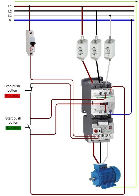
The basic principle behind a start-stop circuit is to use a momentary “start” button to energize a contactor, which then closes its contacts to provide power to the connected device. The circuit is designed to maintain the contactor’s energized state even after the “start” button is released, using a holding circuit. To stop the device, a “stop” button is pressed, which interrupts the holding circuit and de-energizes the contactor, cutting off power to the connected device.
Components of a Start-Stop Circuit
To better understand how a start-stop circuit works, it’s essential to familiarize yourself with its key components:
1. Pushbuttons
Pushbuttons are the primary input devices in a start-stop circuit. They are momentary switches that are normally open (NO) or normally closed (NC). In a start-stop circuit, the “start” button is typically an NO switch, while the “stop” button is an NC switch.
2. Contactors
A contactor is an electrically-controlled switch designed for switching high-current loads. It consists of a coil and a set of contacts. When the coil is energized, it creates a magnetic field that attracts the contacts, closing them and allowing current to flow through the connected device.
3. Overload Protection
Overload protection devices, such as thermal overload relays or electronic overload relays, are used to protect the connected device and the circuit from excessive current. These devices monitor the current flowing through the circuit and trip the contactor if the current exceeds a predetermined value.
4. Indicator Lights
Indicator lights are used to provide visual feedback on the status of the circuit. They can indicate whether the circuit is powered, if the device is running, or if a fault has occurred.

Working Principle of a Start-Stop Circuit
The working principle of a start-stop circuit can be broken down into two main stages:
1. Starting the Device
To start the connected device, the “start” button is pressed, which closes its NO contacts and energizes the contactor coil. Once energized, the contactor closes its main contacts, providing power to the connected device. Simultaneously, the contactor’s auxiliary contacts close, creating a holding circuit that maintains the contactor’s energized state even after the “start” button is released.
2. Stopping the Device
To stop the connected device, the “stop” button is pressed, which opens its NC contacts and interrupts the holding circuit. This de-energizes the contactor coil, causing the main contacts to open and cut off power to the connected device. The auxiliary contacts also open, breaking the holding circuit and preventing the contactor from re-energizing until the “start” button is pressed again.

Control Techniques in Start-Stop Circuits
Several control techniques can be employed in start-stop circuits to enhance their functionality and safety:
1. Three-Wire Control
In a three-wire control system, the “start” and “stop” buttons are wired in series with the contactor coil. This configuration ensures that the contactor can only be energized when the “start” button is pressed and the “stop” button is in its normal (closed) position. Three-wire control provides an added layer of safety by preventing the circuit from restarting automatically after a power interruption.
2. Interlocking
Interlocking is a technique used to prevent the simultaneous operation of multiple devices or to ensure a specific sequence of operations. In a start-stop circuit, interlocking can be achieved by using auxiliary contacts of one contactor to control the operation of another contactor. This technique is particularly useful in applications where multiple motors or devices must operate in a specific order or when the operation of one device depends on the state of another.
3. Emergency Stop
An emergency stop (e-stop) is a safety feature that allows the operator to quickly shut down the system in case of an emergency. E-stop buttons are typically red, mushroom-headed, and latch in the “off” position when pressed. In a start-stop circuit, the e-stop button is wired in series with the “stop” button, ensuring that the circuit is immediately de-energized when the e-stop is activated.

FAQs
-
Q: What is the difference between a contactor and a relay?
A: While both contactors and relays are electrically-controlled switches, contactors are designed for switching high-current loads, such as motors, while relays are used for switching lower-current loads, such as control circuits. -
Q: Can a start-stop circuit be used with three-phase motors?
A: Yes, start-stop circuits can be used with three-phase motors. In this case, the contactor will have three main contacts, one for each phase, and the overload protection device will monitor the current in all three phases. -
Q: What is the purpose of the holding circuit in a start-stop circuit?
A: The holding circuit maintains the contactor’s energized state after the “start” button is released. This allows the connected device to continue running without the need to continuously hold the “start” button. -
Q: How does overload protection work in a start-stop circuit?
A: Overload protection devices monitor the current flowing through the circuit and compare it to a predetermined value. If the current exceeds this value for a specified time, the overload protection device will trip the contactor, cutting off power to the connected device to prevent damage. -
Q: Can a start-stop circuit be controlled remotely?
A: Yes, start-stop circuits can be controlled remotely by using additional components, such as remote control switches or programmable logic controllers (PLCs). These devices can send signals to the start-stop circuit to initiate the starting or stopping sequence from a remote location.
| Component | Function |
|---|---|
| Pushbuttons | Input devices used to start and stop the circuit |
| Contactors | Electrically-controlled switches for switching high-current loads |
| Overload Protection | Devices that protect the circuit and connected device from excessive current |
| Indicator Lights | Provide visual feedback on the status of the circuit |
In conclusion, start-stop circuits are essential control systems used in various industrial applications to safely and efficiently control the operation of electrical devices. By understanding the components, working principles, and control techniques involved in start-stop circuits, designers and technicians can create robust and reliable control systems that meet the specific needs of their applications.


Leave a Reply