What is a Rigid-flex PCB?
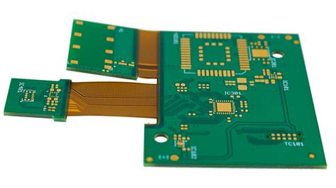
A Rigid-Flex PCB is a printed circuit board that combines both rigid and flexible substrates, allowing for enhanced design flexibility and improved reliability. This unique combination enables the creation of compact, lightweight, and highly functional electronic devices that can withstand harsh environments and repeated flexing.
Advantages of Rigid-Flex PCBs
- Space savings: Rigid-Flex PCBs allow for more compact designs, reducing the overall size and weight of electronic devices.
- Improved reliability: The flexible portions of the PCB eliminate the need for connectors and cables, reducing the risk of connection failures and improving overall reliability.
- Enhanced design flexibility: Rigid-Flex PCBs can be shaped and folded to fit into complex enclosures, enabling innovative product designs.
- Reduced assembly time: With fewer connectors and cables, assembly time is significantly reduced, leading to faster time-to-market and lower production costs.
RAYPCB’s Rigid-Flex PCB Manufacturing Process
At RAYPCB, we employ a state-of-the-art manufacturing process to ensure the highest quality Rigid-Flex PCBs for our clients. Our process includes:
1. Material Selection
We use a variety of high-quality materials to manufacture our Rigid-Flex PCBs, including:
- Polyimide (PI) for the flexible substrate
- FR-4, Rogers, or Isola for the rigid substrate
- Copper foil for the conductive layers
Our engineers work closely with clients to select the most appropriate materials based on their specific requirements, such as temperature range, flexibility, and electrical performance.
2. Design and Layout
Our experienced design team uses advanced CAD tools to create optimal layouts for Rigid-Flex PCBs, ensuring the best possible performance and manufacturability. We consider factors such as:
- Bend radius and bend area design
- Stiffener placement
- Copper balance
- Signal integrity
- Thermal management
3. Fabrication
Our fabrication process involves several key steps:
- Lamination of flexible and rigid substrates
- Drilling and plating of through-holes and vias
- Patterning of conductive layers using photolithography and etching
- Solder mask application and surface finish (ENIG, HASL, or OSP)
- Electrical testing and quality control
4. Assembly
RAYPCB offers full turnkey assembly services for Rigid-Flex PCBs, including:
- SMT (Surface Mount Technology) and THT (Through-Hole Technology) component placement
- Reflow soldering
- Wave Soldering
- Conformal coating
- Functional testing

Applications of Rigid-Flex PCBs
Rigid-Flex PCBs are used in a wide range of industries and applications, including:
- Aerospace and Defense
- Avionics systems
- Satellite communication devices
-
Military wearables
-
Medical Devices
- Implantable devices
- Wearable health monitors
-
Diagnostic equipment
-
Automotive Electronics
- Engine control units
- Infotainment systems
-
Advanced driver assistance systems (ADAS)
-
Consumer Electronics
- Smartphones and tablets
- Smartwatches and fitness trackers
-
VR and AR headsets
-
Industrial Automation
- Robotics and motion control
- Process control systems
- Sensors and data acquisition devices

RAYPCB’s Rigid-Flex PCB Design Guidelines
To ensure the best possible performance and manufacturability of your Rigid-Flex PCBs, follow these design guidelines:
1. Bend Radius and Bend Area Design
- Minimum bend radius should be at least 6 times the thickness of the flexible substrate
- Avoid placing components or vias in the bend area
- Use hatched polygons or teardrops to reinforce the copper traces in the bend area
2. Stiffener Placement
- Use stiffeners to support connectors and other components in the rigid sections
- Ensure a smooth transition between the rigid and flexible sections to minimize stress
3. Copper Balance
- Maintain a consistent copper coverage on both sides of the flexible substrate to prevent warping
- Use copper thieving or copper pours to balance the copper distribution
4. Signal Integrity
- Route high-speed signals on the outer layers of the PCB to minimize crosstalk
- Use differential pairs for high-speed signals to reduce electromagnetic interference (EMI)
- Maintain consistent impedance throughout the signal path
5. Thermal Management
- Use thermal vias to dissipate heat from high-power components
- Place temperature-sensitive components away from heat sources
- Consider using metal-core substrates for enhanced thermal performance

RAYPCB’s Quality Assurance and Testing
At RAYPCB, we are committed to delivering the highest quality Rigid-Flex PCBs to our clients. Our quality assurance process includes:
- 100% electrical testing (continuity, isolation, and resistance)
- Visual inspection for defects and workmanship
- Dimensional verification using automated optical inspection (AOI)
- Impedance testing for controlled impedance designs
- Thermal cycling and flexing tests to ensure reliability
We also offer additional testing services upon request, such as:
- Microsectioning analysis
- Thermal shock testing
- Humidity testing
- Vibration and shock testing
Certifications and Standards
RAYPCB is certified to the following international standards:
- ISO 9001:2015 (Quality Management System)
- ISO 14001:2015 (Environmental Management System)
- IATF 16949:2016 (Automotive Quality Management System)
- IPC-A-600 (Acceptability of Printed Boards)
- IPC-6013 (Qualification and Performance Specification for Flexible Printed Boards)
These certifications demonstrate our commitment to quality, reliability, and customer satisfaction.
Frequently Asked Questions (FAQ)
1. What is the minimum feature size that RAYPCB can achieve for Rigid-Flex PCBs?
We can achieve a minimum trace width and spacing of 0.003″ (75 µm) for the flexible portions and 0.004″ (100 µm) for the rigid portions of the PCB.
2. How many layers can RAYPCB manufacture for Rigid-Flex PCBs?
We can manufacture Rigid-Flex PCBs with up to 20 layers, including both rigid and flexible layers.
3. What is the typical lead time for Rigid-Flex PCBs at RAYPCB?
Our standard lead time for Rigid-Flex PCBs is 3-4 weeks, depending on the complexity of the design and the required quantities. We also offer expedited services for time-sensitive projects.
4. Can RAYPCB provide design support for Rigid-Flex PCBs?
Yes, our experienced design team can provide comprehensive design support, including layout optimization, signal integrity analysis, and manufacturability reviews.
5. What file formats does RAYPCB accept for Rigid-Flex PCB designs?
We accept industry-standard file formats, including Gerber (RS-274X), ODB++, and IPC-2581. We also work with native CAD files from popular design tools such as Altium Designer, Cadence Allegro, and Mentor Graphics PADS.
Conclusion
RAYPCB is your trusted partner for high-quality Rigid-Flex PCB services. With our state-of-the-art manufacturing facilities, experienced engineering team, and commitment to quality, we deliver reliable and cost-effective solutions for a wide range of industries and applications. Contact us today to learn more about how we can help bring your innovative products to life.


Leave a Reply