Introduction to the NE5532 Op-Amp
The NE5532 is a dual op-amp IC that features:
- Low noise: 5nV/√Hz input noise voltage
- High slew rate: 9V/μs
- Wide gain-bandwidth product: 10MHz
- High output current: 10mA
- Wide supply voltage range: ±3V to ±20V
These specifications make the NE5532 ideal for use in audio PreAmp Circuits where low noise and high fidelity are crucial.
Basic NE5532 Preamp Circuit
A basic NE5532 preamp circuit consists of the following components:
- NE5532 op-amp
- Input and feedback resistors
- Input and output coupling capacitors
- Power supply decoupling capacitors
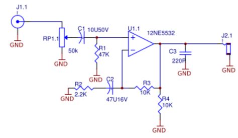
Here’s a schematic of a basic non-inverting NE5532 preamp circuit:
[Insert schematic image]
The gain of this circuit is set by the ratio of the feedback resistor (R2) to the input resistor (R1):
Gain = 1 + (R2 / R1)
For example, if R1 = 1kΩ and R2 = 9kΩ, the gain would be:
Gain = 1 + (9kΩ / 1kΩ) = 10 (20dB)
The input and output coupling capacitors (C1 and C3) block any DC offset and only allow AC signals to pass. The power supply decoupling capacitors (C2 and C4) help to reduce noise and stabilize the power supply.

Inverting NE5532 Preamp Circuit
An inverting NE5532 preamp circuit is similar to the non-inverting version, but with the input signal connected to the inverting input of the op-amp:
[Insert schematic image]
The gain of an inverting preamp circuit is set by the ratio of the feedback resistor (R2) to the input resistor (R1), but with a negative sign:
Gain = -(R2 / R1)
So, for R1 = 1kΩ and R2 = 9kΩ, the gain would be:
Gain = -(9kΩ / 1kΩ) = -10 (-20dB)

Balanced Input NE5532 Preamp Circuit
A balanced input preamp circuit uses both inputs of the NE5532 to accept a balanced input signal, such as from a microphone or balanced line output:
[Insert schematic image]
This circuit uses four resistors (R1-R4) to set the gain and common-mode rejection ratio (CMRR). The gain is set by the ratio of R3/R4 to R1/R2:
Gain = (R3 / R1) = (R4 / R2)
The CMRR is determined by how closely matched the resistor pairs are. Using 1% tolerance resistors can provide a CMRR of about 40dB.

Tone Control NE5532 Preamp Circuit
A tone control preamp circuit allows for adjusting the bass and treble frequencies independently. Here’s an example NE5532 tone control circuit:
[Insert schematic image]
This circuit uses potentiometers (VR1 and VR2) and capacitors (C2 and C3) to create adjustable low-pass and high-pass filters. The corner frequencies and amount of boost/cut are determined by the potentiometer and capacitor values.
Typical values for a bass control might be:
– VR1 = 100kΩ linear pot
– C2 = 22nF
And for a treble control:
– VR2 = 50kΩ linear pot
– C3 = 3.3nF
Loudness Control NE5532 Preamp Circuit
A loudness control boosts the low and high frequencies at low volume levels to compensate for the human ear’s reduced sensitivity to those frequencies at lower volumes. Here’s an NE5532 loudness control circuit:
[Insert schematic image]
This circuit uses a dual-gang potentiometer (VR1a/b) to simultaneously adjust the volume and the amount of low and high-frequency boost. The corner frequencies and amount of boost are set by the capacitor and resistor values.
Typical component values might be:
– VR1 = 50kΩ dual-gang log pot
– R1 = R2 = 10kΩ
– R3 = R4 = 22kΩ
– C1 = C2 = 22nF
Stereo NE5532 Preamp Circuit
To create a stereo preamp, simply build two identical mono preamp circuits, one for the left channel and one for the right. You can use a dual-gang potentiometer to control the volume of both channels simultaneously.
Here’s a block diagram of a stereo NE5532 preamp:
[Insert block diagram image]
NE5532 Preamp PCB Layout Considerations
When designing a PCB for an NE5532 preamp circuit, consider the following:
- Keep signal traces short and direct
- Separate analog and digital ground planes
- Use ground planes to shield sensitive traces
- Place decoupling capacitors close to the NE5532 power pins
- Use metal film resistors for low noise
- Orient input and output connectors to minimize cross-talk
NE5532 vs Other Audio Op-Amps
The NE5532 is just one of many op-amps suitable for audio preamp applications. Some other popular choices include:
| Op-Amp | Key Features |
|---|---|
| OPA2134 | Low noise, low distortion, DIP-8 package |
| LM4562 | Extremely low noise, wide bandwidth, SO-8 |
| AD8599 | Low noise, low distortion, wide bandwidth |
| LT1115 | Low noise, high speed, DIP-8 and SO-8 |
Each op-amp has its own unique specifications and performance characteristics, so be sure to choose the one that best meets your specific application requirements.
FAQ
1. What is the maximum supply voltage for the NE5532?
The NE5532 can operate with supply voltages ranging from ±3V to ±20V. However, for best performance, it is recommended to use supply voltages between ±5V and ±15V.
2. Can I use the NE5532 in a single-supply preamp circuit?
Yes, the NE5532 can be used in single-supply applications by biasing the non-inverting input to half the supply voltage and capacitively coupling the input and output. However, the performance may be slightly compromised compared to a dual-supply configuration.
3. What is the difference between the NE5532 and NE5534 op-amps?
The NE5532 is a dual op-amp, while the NE5534 is a single op-amp. Both have similar electrical characteristics, but the NE5534 has slightly better noise performance. The NE5532 is often preferred for stereo applications where two op-amps are needed.
4. How do I reduce noise in my NE5532 preamp circuit?
To minimize noise in your NE5532 preamp circuit:
– Use a clean, well-regulated power supply
– Keep signal traces short and away from power traces
– Use metal film resistors and high-quality capacitors
– Implement proper grounding and shielding techniques
– Consider using a low-noise op-amp like the NE5534 or OPA2134
5. Can I use the NE5532 for microphone preamplification?
Yes, the NE5532 can be used as a microphone preamp, especially when configured as a balanced input preamp with sufficient gain. However, for very low-noise microphone applications, a dedicated mic preamp IC or a lower-noise op-amp like the OPA1612 or LT1115 may be a better choice.
Conclusion
The NE5532 is a versatile and widely-used op-amp for audio preamplifier circuits. Its low noise, high gain, and wide bandwidth make it an excellent choice for a variety of applications, from simple gain stages to more complex tone and loudness control circuits. By understanding the basic principles of NE5532 preamp design and following best practices for PCB layout and component selection, you can build high-performance audio preamps that meet your specific needs.


Leave a Reply