Introduction to Motion Sensor Circuits
Motion Sensor Circuits are essential components in various applications, from home security systems to automated lighting and energy management. These circuits detect the presence or movement of objects or people within a specific area and trigger an appropriate response, such as activating an alarm, turning on lights, or sending notifications.
In this article, we will explore five DIY ways to build motion detector circuits using different types of sensors and components. By understanding the principles behind these circuits and following the step-by-step instructions, you can create your own motion-sensing devices tailored to your specific needs.
Types of Motion Sensors
Before diving into the DIY motion sensor circuits, let’s take a look at the different types of motion sensors available:
1. Passive Infrared (PIR) Sensors
PIR Sensors detect changes in infrared radiation emitted by objects in their field of view. They are the most common type of motion sensors used in security systems and automatic lighting applications.
2. Microwave Sensors
Microwave sensors emit high-frequency electromagnetic waves and measure the reflected waves to detect motion. They can cover larger areas and are less affected by temperature changes compared to PIR sensors.
3. Ultrasonic Sensors
Ultrasonic sensors work by emitting high-frequency sound waves and measuring the time it takes for the waves to bounce back. They can detect motion in a specific range and are suitable for indoor applications.
4. Dual Technology Sensors
Dual technology sensors combine two or more types of sensing technologies, such as PIR and microwave, to reduce false alarms and improve detection accuracy.

DIY Motion Sensor Circuit 1: PIR Sensor with Arduino
In this project, we will build a motion sensor circuit using a PIR sensor and an Arduino board. The PIR sensor will detect motion, and the Arduino will process the sensor data and trigger an output, such as turning on an LED or activating a relay.
Components Required
- Arduino Uno board
- PIR sensor module (e.g., HC-SR501)
- LED
- 220Ω resistor
- Jumper wires
- Breadboard
Circuit Diagram
[Insert circuit diagram here]
Step-by-Step Instructions
- Connect the VCC pin of the PIR sensor to the 5V pin on the Arduino.
- Connect the GND pin of the PIR sensor to the GND pin on the Arduino.
- Connect the OUT pin of the PIR sensor to digital pin 2 on the Arduino.
- Place the 220Ω resistor between the LED’s anode (longer leg) and digital pin 13 on the Arduino.
- Connect the LED’s cathode (shorter leg) to the GND pin on the Arduino.
- Upload the following code to the Arduino:
int pirPin = 2;
int ledPin = 13;

void setup() {
  pinMode(pirPin, INPUT);
  pinMode(ledPin, OUTPUT);
}

void loop() {
  int pirValue = digitalRead(pirPin);
  if (pirValue == HIGH) {
    digitalWrite(ledPin, HIGH);
    delay(5000);
  } else {
    digitalWrite(ledPin, LOW);
  }
}
- Power the Arduino using a USB cable or an external power supply.
- The LED will turn on for 5 seconds whenever motion is detected by the PIR sensor.

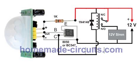
DIY Motion Sensor Circuit 2: Microwave Sensor with Relay
This project demonstrates how to build a motion sensor circuit using a microwave sensor and a relay module. The microwave sensor will detect motion, and the relay will control a high-power load, such as a light bulb or a siren.
Components Required
- Microwave sensor module (e.g., RCWL-0516)
- Relay module (e.g., 5V single-channel)
- Light bulb or siren
- Power supply (12V DC)
- Jumper wires
- Breadboard
Circuit Diagram
[Insert circuit diagram here]
Step-by-Step Instructions
- Connect the VCC pin of the microwave sensor to the 5V pin on the relay module.
- Connect the GND pin of the microwave sensor to the GND pin on the relay module.
- Connect the OUT pin of the microwave sensor to the IN pin on the relay module.
- Connect the positive terminal of the 12V DC power supply to the COM pin on the relay module.
- Connect one end of the light bulb or siren to the NO (Normally Open) pin on the relay module.
- Connect the other end of the light bulb or siren to the negative terminal of the 12V DC power supply.
- Power the circuit using the 12V DC power supply.
- The light bulb or siren will turn on whenever motion is detected by the microwave sensor.

DIY Motion Sensor Circuit 3: Ultrasonic Sensor with Buzzer
In this project, we will create a motion sensor circuit using an ultrasonic sensor and a buzzer. The ultrasonic sensor will detect motion within a specific range, and the buzzer will sound an alarm when motion is detected.
Components Required
- Ultrasonic sensor module (e.g., HC-SR04)
- Buzzer
- Arduino Uno board
- Jumper wires
- Breadboard
Circuit Diagram
[Insert circuit diagram here]
Step-by-Step Instructions
- Connect the VCC pin of the ultrasonic sensor to the 5V pin on the Arduino.
- Connect the GND pin of the ultrasonic sensor to the GND pin on the Arduino.
- Connect the Trig pin of the ultrasonic sensor to digital pin 9 on the Arduino.
- Connect the Echo pin of the ultrasonic sensor to digital pin 10 on the Arduino.
- Connect the positive leg of the buzzer to digital pin 11 on the Arduino.
- Connect the negative leg of the buzzer to the GND pin on the Arduino.
- Upload the following code to the Arduino:
int trigPin = 9;
int echoPin = 10;
int buzzerPin = 11;

void setup() {
  pinMode(trigPin, OUTPUT);
  pinMode(echoPin, INPUT);
  pinMode(buzzerPin, OUTPUT);
}

void loop() {
  long duration, distance;
  digitalWrite(trigPin, LOW);
  delayMicroseconds(2);
  digitalWrite(trigPin, HIGH);
  delayMicroseconds(10);
  digitalWrite(trigPin, LOW);
  duration = pulseIn(echoPin, HIGH);
  distance = duration * 0.034 / 2;

  if (distance < 50) {
    digitalWrite(buzzerPin, HIGH);
    delay(500);
    digitalWrite(buzzerPin, LOW);
    delay(500);
  }
}
- Power the Arduino using a USB cable or an external power supply.
- The buzzer will sound an alarm whenever motion is detected within 50 cm by the ultrasonic sensor.
DIY Motion Sensor Circuit 4: Dual Technology Sensor with GSM Module
This project combines a PIR sensor and a microwave sensor to create a dual technology motion sensor circuit. When motion is detected by both sensors, a GSM module will send an SMS alert to a specified phone number.
Components Required
- PIR sensor module (e.g., HC-SR501)
- Microwave sensor module (e.g., RCWL-0516)
- GSM module (e.g., SIM800L)
- Arduino Uno board
- Jumper wires
- Breadboard
Circuit Diagram
[Insert circuit diagram here]
Step-by-Step Instructions
- Connect the VCC pin of the PIR sensor and the microwave sensor to the 5V pin on the Arduino.
- Connect the GND pin of the PIR sensor and the microwave sensor to the GND pin on the Arduino.
- Connect the OUT pin of the PIR sensor to digital pin 2 on the Arduino.
- Connect the OUT pin of the microwave sensor to digital pin 3 on the Arduino.
- Connect the VCC pin of the GSM module to the 5V pin on the Arduino.
- Connect the GND pin of the GSM module to the GND pin on the Arduino.
- Connect the RX pin of the GSM module to digital pin 10 on the Arduino.
- Connect the TX pin of the GSM module to digital pin 11 on the Arduino.
- Upload the following code to the Arduino:
#include <SoftwareSerial.h>

int pirPin = 2;
int microPin = 3;
int rxPin = 10;
int txPin = 11;

SoftwareSerial sim800l(rxPin, txPin);

void setup() {
  pinMode(pirPin, INPUT);
  pinMode(microPin, INPUT);
  sim800l.begin(9600);
  delay(1000);
}

void loop() {
  int pirValue = digitalRead(pirPin);
  int microValue = digitalRead(microPin);

  if (pirValue == HIGH && microValue == HIGH) {
    sendSMS();
    delay(60000);
  }
}

void sendSMS() {
  sim800l.println("AT+CMGF=1");
  delay(1000);
  sim800l.println("AT+CMGS=\"+1234567890\"");
  delay(1000);
  sim800l.print("Motion detected!");
  delay(100);
  sim800l.write(26);
  delay(1000);
}
- Replace
+1234567890with the phone number you want to receive the SMS alert. - Insert a SIM card into the GSM module and power the Arduino using a USB cable or an external power supply.
- When motion is detected by both the PIR sensor and the microwave sensor, an SMS alert will be sent to the specified phone number.
DIY Motion Sensor Circuit 5: Ultrasonic Sensor with LCD Display
In this project, we will build a motion sensor circuit using an ultrasonic sensor and display the distance of the detected object on an LCD screen.
Components Required
- Ultrasonic sensor module (e.g., HC-SR04)
- 16×2 LCD display
- 10kΩ potentiometer
- Arduino Uno board
- Jumper wires
- Breadboard
Circuit Diagram
[Insert circuit diagram here]
Step-by-Step Instructions
- Connect the VCC pin of the ultrasonic sensor to the 5V pin on the Arduino.
- Connect the GND pin of the ultrasonic sensor to the GND pin on the Arduino.
- Connect the Trig pin of the ultrasonic sensor to digital pin 9 on the Arduino.
- Connect the Echo pin of the ultrasonic sensor to digital pin 10 on the Arduino.
- Connect the VSS pin of the LCD to the GND pin on the Arduino.
- Connect the VDD pin of the LCD to the 5V pin on the Arduino.
- Connect the V0 pin of the LCD to the middle pin of the potentiometer.
- Connect the RS pin of the LCD to digital pin 12 on the Arduino.
- Connect the RW pin of the LCD to the GND pin on the Arduino.
- Connect the E pin of the LCD to digital pin 11 on the Arduino.
- Connect the D4, D5, D6, and D7 pins of the LCD to digital pins 5, 4, 3, and 2 on the Arduino, respectively.
- Connect the outer pins of the potentiometer to the 5V and GND pins on the Arduino.
- Upload the following code to the Arduino:
#include <LiquidCrystal.h>

int trigPin = 9;
int echoPin = 10;

LiquidCrystal lcd(12, 11, 5, 4, 3, 2);

void setup() {
  pinMode(trigPin, OUTPUT);
  pinMode(echoPin, INPUT);
  lcd.begin(16, 2);
}

void loop() {
  long duration, distance;
  digitalWrite(trigPin, LOW);
  delayMicroseconds(2);
  digitalWrite(trigPin, HIGH);
  delayMicroseconds(10);
  digitalWrite(trigPin, LOW);
  duration = pulseIn(echoPin, HIGH);
  distance = duration * 0.034 / 2;

  lcd.clear();
  lcd.setCursor(0, 0);
  lcd.print("Distance:");
  lcd.setCursor(0, 1);
  lcd.print(distance);
  lcd.print(" cm");
  delay(500);
}
- Power the Arduino using a USB cable or an external power supply.
- The LCD will display the distance of the detected object in centimeters.
Frequently Asked Questions (FAQ)
-
What is the difference between a PIR sensor and a microwave sensor?
A PIR sensor detects changes in infrared radiation emitted by objects, while a microwave sensor emits high-frequency electromagnetic waves and measures the reflected waves to detect motion. PIR sensors are more affordable and consume less power, while microwave sensors can cover larger areas and are less affected by temperature changes. -
Can I use a different Arduino board for these projects?
Yes, you can use any Arduino board that is compatible with the sensors and modules used in the projects. Make sure to check the pinout and adjust the code accordingly if needed. -
How can I increase the detection range of the ultrasonic sensor?
The detection range of the ultrasonic sensor depends on the specific model you are using. Some ways to increase the range include using a sensor with a higher power output, ensuring a clear line of sight between the sensor and the detected object, and minimizing interference from other ultrasonic sources. -
What should I do if the GSM module is not sending SMS alerts?
First, make sure that the SIM card is properly inserted and has sufficient credit for sending SMS messages. Check the wiring connections between the GSM module and the Arduino. Verify that the GSM module is receiving a strong signal from the mobile network. If the issue persists, try using a different GSM module or consult the module’s documentation for troubleshooting steps. -
Can I connect multiple motion sensors to a single Arduino board?
Yes, you can connect multiple motion sensors to a single Arduino board. However, you will need to use different digital pins for each sensor and modify the code accordingly to handle the input from each sensor separately.
Conclusion
Building your own motion sensor circuits can be a fun and rewarding experience, whether you are a hobbyist or a professional. By understanding the principles behind different types of motion sensors and following the step-by-step instructions provided in this article, you can create custom motion-sensing devices for various applications.
Remember to always prioritize safety when working with electronic components and to test your circuits thoroughly before deploying them in real-world scenarios. With a little creativity and experimentation, you can develop more advanced motion sensor projects and integrate them into your home automation, security, or energy management systems.


Leave a Reply