What are Varistors?
Varistors are voltage-dependent, nonLinear resistors that exhibit a significant decrease in resistance when subjected to high voltage spikes or transients. They are designed to protect electronic circuits and electrical equipment from damage caused by overvoltage events, such as lightning strikes, switching transients, and electrostatic discharges (ESD).
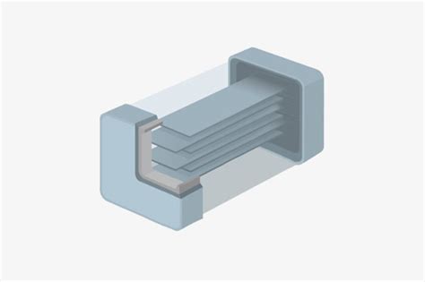
Varistor Construction
A typical varistor consists of a ceramic disc or chip made from a mixture of metal oxides, primarily zinc oxide (ZnO), along with small amounts of other metal oxides like bismuth, cobalt, and manganese. The metal oxide grains are sintered together and sandwiched between two metal electrodes, forming a compact and robust device.
Varistor Symbol and Appearance
The schematic symbol for a varistor resembles two back-to-back zener diodes, indicating its bidirectional voltage-clamping capability. In terms of appearance, varistors come in various sizes and packages, ranging from small surface-mount devices (SMDs) to larger disc or block-type units, depending on their voltage and energy handling capabilities.
How do Varistors Work?
The working principle of varistors relies on their unique nonlinear voltage-current characteristic, which enables them to act as voltage-dependent switches.
Nonlinear Voltage-Current Characteristic
The relationship between voltage and current in a varistor is highly nonlinear. Under normal operating conditions, when the applied voltage is below the varistor’s threshold or “clamping” voltage, the device exhibits a high resistance, typically in the megaohm range, and allows only a small leakage current to flow.
However, when the applied voltage exceeds the clamping voltage, the varistor’s resistance dramatically decreases, often by several orders of magnitude, to a few ohms or less. This sudden drop in resistance allows the varistor to conduct a large current, effectively shunting the excess energy away from the protected circuit.
Voltage Clamping and Energy Absorption
As the varistor conducts the surge current, it clamps the voltage across its terminals to a safe level, preventing the voltage from rising further and damaging the connected equipment. The varistor absorbs the excess energy associated with the transient event, dissipating it as heat.
Once the transient voltage subsides and falls below the clamping voltage, the varistor’s resistance returns to its high value, and the device recovers to its normal state, ready to protect against future overvoltage events.

Varistor Characteristics and Parameters
To effectively select and apply varistors in circuit protection, it is essential to understand their key characteristics and parameters.
Clamping Voltage (Vc)
The clamping voltage, also known as the breakdown voltage or varistor voltage, is the voltage at which the varistor begins to conduct significant current and clamp the transient voltage. It is typically specified at a specific current, such as 1 mA or 10 mA, and is an important parameter in determining the protection level provided by the varistor.
Maximum Continuous Operating Voltage (MCOV)
The maximum continuous operating voltage (MCOV) is the highest steady-state voltage that can be applied to the varistor without causing degradation or damage over its lifetime. It is typically specified as a root mean square (RMS) value for AC applications and a DC value for DC applications. Operating the varistor below its MCOV ensures reliable and long-term performance.
Peak Current (Ip) and Energy Absorption Capacity
The peak current (Ip) represents the maximum instantaneous current that the varistor can handle during a transient event. It is usually specified for a specific waveform, such as an 8/20 μs or 10/1000 μs pulse, which defines the rise time and duration of the current pulse.
The energy absorption capacity, expressed in joules (J), indicates the maximum amount of energy the varistor can absorb without failing. It is determined by the varistor’s size, material composition, and construction.
Response Time
Varistors have an extremely fast response time, typically in the range of a few nanoseconds. This quick response allows them to clamp voltage spikes and transients effectively, preventing damage to sensitive electronic components.
Leakage Current
Leakage current refers to the small current that flows through the varistor when the applied voltage is below the clamping voltage. It is an important parameter to consider, especially in low-power applications, as excessive leakage current can lead to unwanted power dissipation and affect the overall efficiency of the system.

Varistor Applications
Varistors find widespread use in various electrical and electronic applications for overvoltage protection. Some common applications include:
Power Supply Protection
Varistors are commonly used in power supplies to protect against voltage spikes and transients on the AC mains input. They are connected in parallel with the input to clamp any overvoltage events and prevent damage to the power supply components, such as rectifiers, filters, and regulators.
Surge Protection Devices (SPDs)
Varistors are key components in surge protection devices (SPDs) used in residential, commercial, and industrial settings. SPDs are installed in electrical panels, power distribution systems, and at the point of entry of incoming power lines to protect against lightning strikes and other high-energy transients.
Electronic Circuit Protection
In electronic circuits, varistors are used to protect sensitive components, such as microprocessors, memory devices, and communication interfaces, from voltage spikes and ESD events. They are often placed near connector pins, power supply lines, and other potential entry points for transient voltages.
Automotive Electronics
Varistors play a crucial role in protecting automotive electronic systems from voltage spikes caused by load dumps, alternator noise, and other electrical disturbances. They are used in various automotive applications, including engine control units (ECUs), infotainment systems, and safety-critical functions like anti-lock braking systems (ABS) and airbag controls.
Telecommunications Equipment
In telecommunications equipment, varistors are employed to protect sensitive components from voltage surges induced by lightning strikes on communication lines. They are used in line cards, modems, and other telecom interfaces to ensure reliable operation and prevent damage to expensive equipment.

Varistor Selection Considerations
When selecting a varistor for a specific application, several key factors need to be considered to ensure optimal performance and protection.
Voltage Rating
The varistor’s voltage rating should be chosen based on the maximum continuous operating voltage (MCOV) of the system or circuit being protected. The varistor’s clamping voltage should be higher than the normal operating voltage range but lower than the maximum voltage that the protected components can withstand.
Current and Energy Rating
The peak current and energy absorption capacity of the varistor should be selected based on the expected magnitude and duration of the transient events in the application. It is essential to choose a varistor with sufficient current and energy ratings to handle the worst-case scenario without failing.
Response Time
For applications with fast-rising transients, such as ESD events, it is crucial to select a varistor with a fast response time to ensure effective clamping and protection.
Environmental Factors
The operating temperature range, humidity, and other environmental factors should be considered when selecting a varistor. Some varistors are designed for high-temperature or harsh environments, while others may have limitations in extreme conditions.
Size and Packaging
The physical size and packaging of the varistor should be compatible with the circuit layout and available space. Surface-mount devices (SMDs) are commonly used in compact electronic circuits, while larger disc or block-type varistors are suitable for high-energy applications or power line protection.
Varistor Installation and Usage Guidelines
To ensure the proper functioning and reliability of varistors, follow these installation and usage guidelines:
Placement and Connection
Varistors should be placed as close as possible to the components or circuits they are intended to protect. This minimizes the inductance in the connection path and ensures effective clamping of transient voltages. The varistor should be connected in parallel with the protected circuit, with short and low-impedance connections to minimize any additional voltage drop during a surge event.
Grounding and Shielding
Proper grounding and shielding practices are essential for effective transient suppression. The varistor’s ground connection should be low-impedance and connected to a common ground point to prevent ground loops and potential differences. In some cases, additional shielding may be required to protect against radiated electromagnetic interference (EMI) from the varistor during a surge event.
Thermal Management
Varistors dissipate the absorbed energy as heat during a transient event. In applications with frequent or high-energy transients, adequate thermal management should be provided to prevent overheating and ensure reliable operation. This may involve the use of heat sinks, thermal pads, or other cooling methods to dissipate the generated heat effectively.
Redundancy and Coordination
In critical applications, it is often recommended to use multiple varistors in parallel or in combination with other surge protection devices, such as gas discharge tubes (GDTs) or transient voltage suppressors (TVSs), to provide redundancy and improved protection. Proper coordination between these devices should be ensured to optimize their performance and avoid any interference or unintended interactions.
Varistor Failure Modes and Precautions
While varistors are designed to protect against overvoltage events, they can fail under certain conditions. Understanding the common failure modes and taking appropriate precautions can help minimize the risk of varistor failure and ensure reliable protection.
Thermal Runaway
Thermal runaway is a condition where the varistor’s temperature increases uncontrollably due to excessive current flow or repeated high-energy transients. As the temperature rises, the varistor’s resistance decreases further, leading to even higher current flow and potentially catastrophic failure. To prevent thermal runaway, it is essential to select a varistor with an appropriate energy rating and provide adequate cooling or thermal management.
Ageing and Degradation
Varistors can degrade over time due to various factors, such as repeated surge events, high operating temperatures, and exposure to moisture or other environmental stresses. Degradation can lead to changes in the varistor’s characteristics, such as increased leakage current, reduced clamping voltage, and decreased energy absorption capacity. Regular monitoring and replacement of varistors in critical applications can help mitigate the risk of failures due to ageing and degradation.
Short-Circuit Failure
In rare cases, a varistor may fail short-circuit, effectively creating a low-resistance path between its terminals. This can occur due to excessive energy absorption, mechanical damage, or manufacturing defects. A short-circuited varistor can no longer provide protection and may cause further damage to the connected circuitry. Fuses, circuit breakers, or other overcurrent protection devices should be used in series with the varistor to prevent damage in case of a short-circuit failure.
Varistor Testing and Monitoring
To ensure the continued effectiveness and reliability of varistors, regular testing and monitoring are recommended, especially in critical applications.
Visual Inspection
Periodic visual inspection of varistors can help identify any physical damage, such as cracks, chips, or discoloration, which may indicate potential failure or degradation. Damaged varistors should be replaced promptly to maintain the integrity of the protection system.
Leakage Current Monitoring
Monitoring the leakage current of varistors can provide insight into their health and performance. An increase in leakage current over time may indicate degradation or impending failure. Leakage current monitoring can be performed using specialized equipment or by incorporating current-sensing circuits in the system design.
Surge Testing
Surge testing involves subjecting varistors to controlled transient voltage or current pulses to assess their clamping performance and energy absorption capability. This testing can be done as part of the manufacturing quality control process or during periodic maintenance to ensure that the varistors continue to meet their specified ratings and provide adequate protection.
Frequently Asked Questions (FAQ)
-
Q: Can varistors be used for both AC and DC applications?
A: Yes, varistors can be used for both AC and DC applications. However, it is important to select a varistor with the appropriate voltage rating and maximum continuous operating voltage (MCOV) for the specific application. -
Q: How do varistors differ from other surge protection devices, such as gas discharge tubes (GDTs) and transient voltage suppressors (TVSs)?
A: Varistors, GDTs, and TVSs are all used for surge protection but have different operating principles and characteristics. Varistors are voltage-dependent resistors that clamp the voltage and absorb energy, GDTs are gas-filled devices that ionize and conduct when the voltage exceeds a certain threshold, and TVSs are semiconductor-based devices that clamp the voltage using avalanche or zener breakdown. Each device has its own advantages and limitations, and the choice depends on the specific application requirements. -
Q: Can varistors be connected in series or parallel for increased protection?
A: Varistors can be connected in parallel to increase the current handling capacity and energy absorption capability. However, connecting varistors in series is generally not recommended, as it can lead to uneven voltage distribution and potential failure. If higher voltage protection is required, it is better to choose a varistor with a higher voltage rating or use a combination of different surge protection devices. -
Q: How do I select the appropriate varistor for my application?
A: To select the appropriate varistor, consider the following factors: voltage rating (MCOV), clamping voltage, peak current, energy absorption capacity, response time, and environmental conditions. Determine the maximum continuous operating voltage and the expected transient voltage levels in your application, and choose a varistor with ratings that exceed these requirements. Also, consider the available space, thermal management, and any specific application requirements. -
Q: What should I do if a varistor fails in my system?
A: If a varistor fails, it is important to identify the root cause of the failure and take appropriate corrective actions. Check for any signs of physical damage, overheating, or short-circuit failure. Replace the failed varistor with a new one of the same or compatible ratings. Review the system design and operating conditions to ensure that the varistor is not being subjected to stresses beyond its ratings. Consider implementing additional protection measures, such as fuses or circuit breakers, to prevent damage in case of future failures.
Conclusion
Metal oxide varistors (MOVs) are essential components for protecting electrical and electronic systems from voltage spikes, transients, and surges. Their unique nonlinear voltage-current characteristic allows them to clamp the voltage and absorb excess energy, ensuring the safety and reliability of the protected devices and equipment.
Understanding the working principles, characteristics, and applications of varistors is crucial for selecting the appropriate device and implementing effective surge protection solutions. By considering factors such as voltage rating, energy absorption capacity, response time, and environmental conditions, designers can choose the most suitable varistor for their specific application needs.
Proper installation, usage, and monitoring of varistors are essential to ensure their optimal performance and long-term reliability. Regular testing, visual inspection, and leakage current monitoring can help identify potential issues and prevent failures.
As technology advances and the demand for reliable surge protection grows, varistors will continue to play a vital role in safeguarding electrical and electronic systems from the damaging effects of overvoltage events. By staying informed about the latest developments and best practices in varistor technology, engineers and technicians can design and maintain robust and resilient protection solutions for a wide range of applications.


Leave a Reply