Introduction to Circuit Stripboards
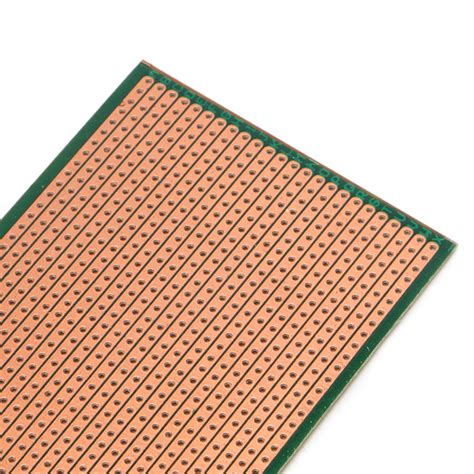
A stripboard, also known as a veroboard, is a widely used prototyping board for creating electronic circuits. It consists of a perforated insulating board with parallel copper strips running along one side, allowing for easy soldering of components and creation of electrical connections. Stripboards offer a convenient and flexible way to design and build circuits without the need for custom PCB fabrication.
In this article, we will explore the process of making circuits on a stripboard, including the tools and techniques required, best practices for component placement and soldering, and tips for troubleshooting and optimizing your circuits.
Advantages of Using Stripboards for Circuit Design
- Cost-effective: Stripboards are an affordable option for prototyping and small-scale projects compared to custom PCB fabrication.
- Flexibility: Stripboards allow for easy modification and experimentation with circuit designs, as components can be easily added, removed, or rearranged.
- Accessibility: Stripboards are widely available and can be used by hobbyists and professionals alike, without requiring specialized equipment or knowledge.
- Quick turnaround: Circuits can be created and tested on stripboards relatively quickly, enabling faster iteration and development cycles.
Tools and Materials Required
To get started with making circuits on a stripboard, you will need the following tools and materials:
- Stripboard: Choose a stripboard with the appropriate size and number of copper strips for your circuit design.
- Soldering iron: A soldering iron with a fine tip is essential for precise soldering of components onto the stripboard.
- Solder: Use a high-quality solder with a suitable diameter for electronic work, typically around 0.5mm to 0.8mm.
- Wire cutters: Wire cutters are used to trim component leads and cut wires to the desired length.
- Needle-nose pliers: Pliers are helpful for bending component leads and holding components in place during soldering.
- Desoldering tools: In case of mistakes or modifications, desoldering tools such as a desoldering pump or desoldering wick can be used to remove solder and components from the stripboard.
- Multimeter: A multimeter is useful for testing continuity, measuring voltages, and debugging circuits.
- Components: Gather all the necessary components for your circuit, such as resistors, capacitors, transistors, and integrated circuits.

Planning Your Circuit Layout
Before diving into the actual construction of your circuit on the stripboard, it’s crucial to plan your circuit layout carefully. Here are some steps to follow:
-
Create a schematic diagram: Start by designing your circuit using a schematic capture software or by drawing it on paper. Ensure that your schematic is accurate and includes all the necessary components and connections.
-
Translate the schematic to stripboard layout: Analyze your schematic and determine the best way to arrange the components on the stripboard. Consider factors such as component size, pin spacing, and signal flow.
-
Optimize component placement: Aim to minimize the distance between connected components to reduce stray capacitance and interference. Group related components together for better organization and readability.
-
Plan the copper strip cuts: Identify the points where you need to make breaks in the copper strips to create isolated sections for your circuit. Mark these points on your stripboard layout.
-
Consider power supply and grounding: Determine the appropriate locations for power supply connections and grounding points on the stripboard. Ensure that these connections are easily accessible and well-labeled.
Tips for Effective Stripboard Layout
- Keep signal paths as short as possible to minimize noise and interference.
- Use consistent spacing between components and copper strips for a clean and organized layout.
- Avoid crossing wires or component leads whenever possible to prevent short circuits.
- Provide adequate clearance around components for easy soldering and future modifications.
- Use color-coded wires or labels to identify different sections or signals in your circuit.

Preparing the Stripboard
Once you have finalized your circuit layout, it’s time to prepare the stripboard for component placement and soldering. Follow these steps:
-
Cut the stripboard: If necessary, cut the stripboard to the desired size using a hacksaw or a specialized PCB Cutting tool. Ensure that the cuts are straight and clean.
-
Make copper strip breaks: Using a hand drill or a stripboard cutter, make breaks in the copper strips at the points marked in your layout. These breaks isolate sections of the strips and prevent unwanted connections.
-
Clean the stripboard: Clean the stripboard thoroughly with isopropyl alcohol and a lint-free cloth to remove any dirt, grease, or oxidation from the copper strips. This ensures better solderability and reduces the risk of poor connections.
-
Secure the stripboard: If needed, secure the stripboard to your work surface using a PCB holder or clamps to prevent it from moving during the soldering process.

Soldering Components onto the Stripboard
With the stripboard prepared, you can now start soldering the components onto the board. Follow these guidelines for successful soldering:
-
Position the components: Place the components on the stripboard according to your planned layout. Ensure that the component leads are inserted through the correct holes and that the components are seated flush against the board.
-
Bend the component leads: Using needle-nose pliers, gently bend the component leads on the underside of the stripboard to hold the components in place. Make sure the leads are not touching adjacent copper strips unintentionally.
-
Apply solder: Heat the soldering iron and apply a small amount of solder to the tip to ensure good heat transfer. Touch the soldering iron to the component lead and the copper strip simultaneously, allowing them to heat up for a couple of seconds.
-
Create the solder joint: Feed a small amount of solder into the junction between the component lead and the copper strip. The solder should flow smoothly and create a shiny, concave joint. Avoid applying too much solder, as it can cause bridges between adjacent strips.
-
Trim the excess leads: After soldering, use wire cutters to trim the excess component leads close to the solder joint. This prevents short circuits and improves the overall appearance of your circuit.
Soldering Best Practices
- Keep the soldering iron tip clean and tinned for optimal heat transfer and consistent solder joints.
- Use the appropriate soldering iron temperature for the components and solder type you are working with.
- Apply heat to both the component lead and the copper strip simultaneously to ensure a strong and reliable solder joint.
- Avoid breathing in the soldering fumes by working in a well-ventilated area or using a fume extractor.
- Inspect each solder joint visually to ensure it is shiny, smooth, and properly formed.
Testing and Troubleshooting Your Circuit
After completing the soldering process, it’s essential to test your circuit thoroughly to ensure its functionality and identify any issues. Here’s how to approach testing and troubleshooting:
-
Visual inspection: Carefully examine your soldered circuit for any visible defects, such as bridges between copper strips, cold solder joints, or misplaced components. Correct any issues before proceeding with further testing.
-
Continuity testing: Use a multimeter to check the continuity between different points in your circuit. Verify that the expected connections are intact and that there are no unintended short circuits.
-
Power-on testing: Apply power to your circuit and measure the voltage levels at critical points using a multimeter. Compare the measured values with your expected values based on your circuit design.
-
Functional testing: Test the overall functionality of your circuit by providing the necessary inputs and observing the outputs. Verify that the circuit behaves as intended and meets your design specifications.
Common Troubleshooting Techniques
If your circuit is not functioning as expected, here are some common troubleshooting techniques:
- Double-check your circuit schematic and layout for any design errors or discrepancies.
- Verify that all components are placed correctly and oriented in the right direction.
- Check for loose or damaged components, and replace them if necessary.
- Inspect solder joints for poor connections, bridges, or cold joints, and resolder if required.
- Use a multimeter to measure voltages, currents, and resistances at different points in the circuit to isolate the problem area.
- Refer to datasheets and application notes for the specific components used in your circuit for guidance on proper usage and troubleshooting.
Optimizing and Enhancing Your Stripboard Circuit
Once you have a functional circuit on your stripboard, you may want to consider optimizing and enhancing its performance. Here are some techniques to explore:
-
Minimize noise and interference: Implement proper grounding techniques, use decoupling capacitors, and keep sensitive signal traces away from sources of noise to improve signal integrity.
-
Improve power distribution: Use thicker copper traces or dedicated power buses for high-current paths to minimize voltage drops and ensure stable power delivery to all components.
-
Add protection circuitry: Incorporate protective components such as fuses, transient voltage suppressors, or reverse polarity protection to safeguard your circuit from damage due to overloads, surges, or incorrect connections.
-
Consider thermal management: For circuits with high-power components, use heat sinks or provide adequate ventilation to dissipate heat and prevent overheating.
-
Implement modularity: Design your stripboard circuit in a modular fashion, allowing for easy replacement or upgrades of specific sections without affecting the entire circuit.
Advanced Stripboard Techniques
As you gain experience with making circuits on stripboards, you can explore more advanced techniques to enhance your designs:
- Use wire jumpers: Create connections between non-adjacent copper strips using insulated wire jumpers to maximize space utilization and simplify routing.
- Employ multi-layer stripboards: For complex circuits, consider using multi-layer stripboards that offer additional routing options and higher component density.
- Incorporate surface-mount components: Adapt your stripboard design to accommodate surface-mount components, which offer smaller footprints and improved performance compared to through-hole components.
- Integrate with other modules: Combine your stripboard circuit with other modules, such as displays, sensors, or communication interfaces, to create more sophisticated projects.
Frequently Asked Questions (FAQ)
-
Can I reuse a stripboard for multiple projects?
Yes, you can reuse a stripboard for multiple projects by desoldering the components and cleaning the board thoroughly. However, keep in mind that repeated soldering and desoldering may degrade the quality of the copper strips over time. -
How do I choose the right size of stripboard for my circuit?
The size of the stripboard depends on the complexity of your circuit and the number of components involved. Estimate the space required for your components and routing, and select a stripboard that provides sufficient space with some extra room for modifications or additions. -
Can I mix different types of components on the same stripboard?
Yes, you can mix different types of components, such as through-hole and surface-mount components, on the same stripboard. However, ensure that you have the appropriate soldering techniques and tools to handle each type of component effectively. -
How do I create a professional-looking stripboard circuit?
To create a professional-looking stripboard circuit, follow best practices such as maintaining consistent spacing, using straight traces, and keeping the layout clean and organized. Label your components and connections clearly, and consider using wire colors or cable management techniques for better readability. -
What safety precautions should I take when working with stripboards?
When working with stripboards, always prioritize safety. Use a soldering iron with a grounded tip to prevent electric shocks, and work in a well-ventilated area to avoid inhaling solder fumes. Wear protective eyewear and handle sharp tools and hot soldering irons with care. Ensure that your circuit is properly powered and does not exceed the maximum ratings of the components used.
Conclusion
Making circuits on a stripboard is a versatile and rewarding skill for anyone interested in electronics prototyping and DIY projects. By following the guidelines and best practices outlined in this article, you can create functional and reliable circuits on stripboards efficiently.
Remember to plan your circuit layout carefully, prepare the stripboard properly, and solder the components with precision and care. Testing and troubleshooting your circuit is an essential step to ensure its functionality and identify any issues.
As you gain experience, don’t hesitate to explore advanced techniques and optimize your stripboard circuits for better performance and reliability. With practice and persistence, you can unlock the full potential of stripboards and bring your electronic projects to life.
Happy circuit building!
Here are some resources for further learning:
| Resource | Description |
|---|---|
| Online Tutorials | Websites like Instructables, Hackaday, and Adafruit offer a wide range of tutorials and projects related to stripboard circuits. |
| Electronics Forums | Participate in online forums such as EEVblog, Arduino Forum, or Electro-Tech-Online to ask questions, share ideas, and learn from experienced electronics enthusiasts. |
| Books and Magazines | Explore books and magazines dedicated to electronics, such as “Make: Electronics” by Charles Platt or “Practical Electronics for Inventors” by Paul Scherz, to deepen your understanding of circuit design and construction techniques. |
| Local Makerspaces | Join a local makerspace or hackerspace to access tools, resources, and collaborate with like-minded individuals passionate about electronics and DIY projects. |
| Online Courses | Enroll in online courses on platforms like Udemy, Coursera, or edX to learn electronics fundamentals, PCB design, and advanced circuit techniques from industry experts. |
By continuously expanding your knowledge and skills through these resources, you can become proficient in making circuits on stripboards and tackle increasingly complex projects with confidence.


Leave a Reply