1. Understanding the Basics of LEDs
1.1 What are LEDs?
LEDs are semiconductor devices that emit light when an electric current passes through them. They are made from materials such as gallium arsenide (GaAs) or gallium nitride (GaN), which determine the color of the light emitted. LEDs are known for their high efficiency, long lifespan, and low power consumption compared to traditional lighting sources like incandescent bulbs.
1.2 How do LEDs work?
LEDs work on the principle of electroluminescence. When a forward voltage is applied to an LED, electrons flow from the cathode (negative terminal) to the anode (positive terminal). As the electrons move across the junction between the n-type and p-type semiconductor materials, they release energy in the form of photons, which we perceive as light.
1.3 LED Characteristics
LEDs have several important characteristics that designers must consider:
| Characteristic | Description |
|---|---|
| Forward Voltage | The voltage required to make the LED conduct and emit light. Typically ranges from 1.8V to 3.3V depending on the LED color and material. |
| Forward Current | The current that flows through the LED when the forward voltage is applied. Exceeding the maximum rated current can damage the LED. |
| Luminous Intensity | The amount of light emitted by the LED, measured in candela (cd). |
| Viewing Angle | The angle at which the LED’s light output is half of its maximum intensity. Wider viewing angles result in a more dispersed light distribution. |
2. Choosing the Right LEDs for Your Circuit
2.1 LED Types and Packages
LEDs come in various types and packages to suit different applications. Some common types include:
- Through-hole LEDs: Traditional LEDs with long leads that are inserted through holes in the PCB and soldered on the back side.
- Surface Mount LEDs (SMD): Smaller LEDs that are mounted directly on the surface of the PCB, enabling more compact designs.
- High-Power LEDs: LEDs designed to handle higher currents and produce more light output, often used in lighting applications.
- RGB LEDs: LEDs that can produce a wide range of colors by combining red, green, and blue LEDs in a single package.
2.2 Choosing the Right LED for Your Application
When selecting LEDs for your circuit, consider the following factors:
- Wavelength (color) of the LED
- Luminous intensity and viewing angle
- Forward voltage and current requirements
- Package type and size
- Thermal management requirements
- Cost and availability
2.3 LED Datasheets
Always refer to the LED’s datasheet provided by the manufacturer for detailed specifications, electrical characteristics, and recommended operating conditions. The datasheet will help you determine the appropriate current limiting resistor values and ensure proper operation of the LED in your circuit.

3. Current Limiting Resistors
3.1 The Need for Current Limiting Resistors
LEDs are current-driven devices, meaning their brightness is determined by the amount of current flowing through them. However, LEDs have a low dynamic resistance, which means that a small change in voltage can result in a large change in current. Without proper current control, an LED can draw excessive current, leading to overheating and permanent damage.
To prevent this, current limiting resistors are used in series with LEDs to regulate the current flow.
3.2 Calculating the Current Limiting Resistor Value
To calculate the value of the current limiting resistor, you need to know the following:
- The LED’s forward voltage (Vf)
- The LED’s maximum forward current (If)
- The supply voltage (Vs)
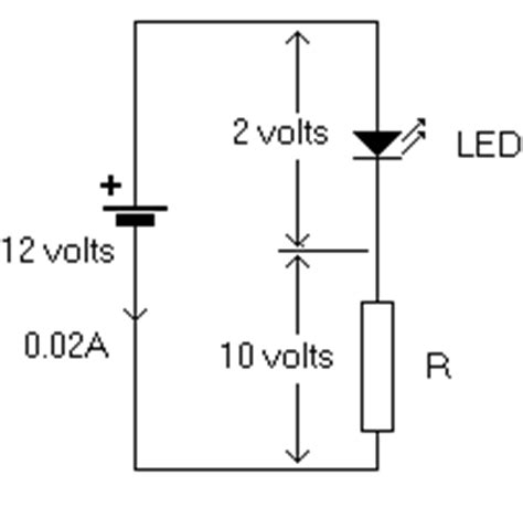
Using Ohm’s Law, the resistor value can be calculated as:
R = (Vs – Vf) / If
For example, if you have an LED with a forward voltage of 2.1V, a maximum forward current of 20mA, and a supply voltage of 5V, the resistor value would be:
R = (5V – 2.1V) / 0.02A = 145Ω
In practice, you would choose the nearest standard resistor value, such as 150Ω.
3.3 Resistor Power Rating
In addition to the resistance value, you must also consider the power rating of the resistor. The power dissipated by the resistor can be calculated using the formula:
P = I2 × R
For the previous example, the power dissipated by the 150Ω resistor would be:
P = (0.02A)2 × 150Ω = 0.06W
Choose a resistor with a power rating higher than the calculated value to ensure reliable operation and prevent overheating.

4. LED Series and Parallel Connections
4.1 Series Connection
In a series connection, LEDs are connected end-to-end, with the anode of one LED connected to the cathode of the next. The same current flows through all the LEDs in the series, and the total voltage drop is the sum of the individual LED forward voltages.
Advantages of series connection:
– Ensures equal current through all LEDs
– Requires only one current limiting resistor
Disadvantages of series connection:
– Higher voltage drop across the LED string
– If one LED fails, the entire string will stop working
4.2 Parallel Connection
In a parallel connection, the anodes of all LEDs are connected together, and the cathodes are connected together. Each LED has its own current path, and the total current is the sum of the individual LED currents.
Advantages of parallel connection:
– Lower voltage drop compared to series connection
– If one LED fails, the others will continue to work
Disadvantages of parallel connection:
– Requires a current limiting resistor for each LED
– Slight variations in LED forward voltages can cause uneven current distribution
4.3 Combining Series and Parallel Connections
In some cases, a combination of series and parallel connections can be used to achieve the desired voltage and current requirements while minimizing the number of current limiting resistors needed.
For example, if you have a 12V supply and want to power 12 LEDs with a forward voltage of 2V each, you can create three parallel strings of four LEDs in series. Each series string would have a total voltage drop of 8V and require a single current limiting resistor.

5. LED Drivers and Control Circuits
5.1 Constant Current LED Drivers
For more advanced LED lighting applications, constant current LED drivers are often used instead of simple current limiting resistors. These drivers provide a regulated constant current to the LEDs, ensuring stable brightness and protecting the LEDs from voltage fluctuations.
Examples of constant current LED drivers include:
– Linear regulators (e.g., LM317)
– Switching regulators (e.g., buck converters)
– Dedicated LED driver ICs (e.g., MAX16832)
5.2 PWM Dimming
Pulse Width Modulation (PWM) is a technique used to control the brightness of LEDs by rapidly turning them on and off at a high frequency. By varying the duty cycle (the ratio of on-time to off-time), the perceived brightness of the LED can be adjusted.
PWM dimming offers several advantages over analog dimming methods:
– Maintains color consistency across the dimming range
– Higher efficiency, as the LED is either fully on or fully off
– Easy to implement using microcontrollers or dedicated PWM controllers
5.3 LED Multiplexing
LED multiplexing is a technique used to control multiple LEDs using a reduced number of microcontroller pins. It works by rapidly switching between different LEDs or groups of LEDs, taking advantage of the persistence of vision to create the illusion that all LEDs are on simultaneously.
Multiplexing is commonly used in applications such as LED matrices, seven-segment displays, and LED cube displays.
6. PCB Design Considerations for LED Circuits
6.1 Trace Width and Thickness
When designing a PCB for LED circuits, it’s essential to consider the trace width and thickness to ensure adequate current carrying capacity and minimize voltage drop. The required trace width depends on factors such as the maximum current, the thickness of the copper layer, and the allowable temperature rise.
Online trace width calculators or PCB design software can help determine the appropriate trace width for your specific requirements.
6.2 Thermal Management
LEDs generate heat during operation, which can affect their performance and lifespan. Proper thermal management is crucial to ensure reliable operation and prevent premature failure.
Some thermal management techniques for LED circuits include:
– Using metal-core PCBs (MCPCBs) with high thermal conductivity
– Incorporating heatsinks or thermal pads to dissipate heat
– Providing adequate ventilation or active cooling (e.g., fans) in enclosures
– Designing the PCB layout to minimize thermal resistance and promote heat dissipation
6.3 Electromagnetic Interference (EMI)
LED circuits, particularly those with PWM dimming or switching regulators, can generate electromagnetic interference (EMI) that can affect nearby electronic devices. To minimize EMI, consider the following:
- Keep high-frequency traces short and away from sensitive circuits
- Use ground planes to provide a low-impedance return path for high-frequency currents
- Implement proper shielding and grounding techniques
- Follow good PCB layout practices, such as minimizing loop areas and using decoupling capacitors
7. Testing and Troubleshooting LED Circuits
7.1 Visual Inspection
Before powering up an LED circuit, always perform a visual inspection to check for:
– Correct component placement and orientation
– Proper soldering and absence of solder bridges or cold joints
– Damaged or missing components
– Correct wiring and connections
7.2 Multimeter Checks
Use a multimeter to verify the following:
– Continuity between components and traces
– Forward voltage drop across LEDs
– Resistance of current limiting resistors
– Supply voltage levels
7.3 Current Measurements
To ensure LEDs are operating within their specified current limits, use a multimeter or current probe to measure the current flowing through the LEDs. Compare the measured values with the expected values based on your calculations or simulations.
7.4 Thermal Monitoring
Monitor the temperature of LEDs and their surroundings during operation to ensure they are within safe limits. Use temperature sensors, thermal imaging cameras, or infrared thermometers to measure the temperature and identify any hot spots that may indicate inadequate thermal management.
7.5 Troubleshooting Common Issues
Some common issues with LED circuits and their potential solutions include:
| Issue | Possible Causes | Solutions |
|---|---|---|
| LED does not light up | – Incorrect polarity – Open circuit – Damaged LED |
– Check and correct LED polarity – Verify continuity and connections – Replace the LED |
| LED is dim or flickering | – Insufficient current – Loose connections – PWM frequency too low |
– Check and adjust current limiting resistor value – Ensure proper soldering and connections – Increase PWM frequency |
| LEDs have uneven brightness | – Variations in LED forward voltage – Uneven current distribution |
– Use matched LEDs with similar forward voltages – Implement current mirrors or individual current control |
| LEDs are overheating | – Excessive current – Inadequate thermal management |
– Verify current limiting resistor values – Improve heatsinking or ventilation |
Frequently Asked Questions (FAQ)
1. Can I connect LEDs directly to a battery without a current limiting resistor?
No, it is not recommended to connect LEDs directly to a battery without a current limiting resistor. LEDs have a low dynamic resistance, and without proper current control, they can draw excessive current, leading to overheating and permanent damage. Always use a current limiting resistor or a constant current LED driver to ensure safe and reliable operation.
2. How do I determine the polarity of an LED?
The polarity of an LED can be determined by looking at its physical structure. The longer lead is typically the anode (positive), while the shorter lead is the cathode (negative). Additionally, the cathode side of the LED package may have a flat edge or a notch to indicate polarity.
3. Can I use a higher value current limiting resistor than calculated?
Yes, you can use a higher value current limiting resistor than calculated. Using a higher value resistor will reduce the current flowing through the LED, resulting in lower brightness. However, ensure that the current is still above the LED’s minimum operating current to maintain reliable operation.
4. How do I control multiple LEDs with different colors using a single microcontroller pin?
To control multiple LEDs with different colors using a single microcontroller pin, you can use the LED multiplexing technique. Connect the anodes of the LEDs to the microcontroller pin through current limiting resistors, and connect the cathodes to individual transistors or dedicated LED driver ICs. By rapidly switching the transistors or drivers on and off, you can control the individual LEDs and create various color combinations.
5. What is the lifespan of an LED, and how can I maximize it?
The lifespan of an LED depends on factors such as the LED type, operating current, temperature, and environmental conditions. Typical lifespans range from 25,000 to 100,000 hours or more. To maximize the lifespan of an LED:
- Operate the LED within its specified current and voltage limits
- Ensure proper thermal management to prevent overheating
- Use current limiting resistors or constant current drivers to regulate current
- Protect the LED from excessive vibration, moisture, and other environmental factors
- Use high-quality LEDs from reputable manufacturers
By understanding these seven crucial aspects of LEDs circuit boards, you can design, build, and troubleshoot LED circuits with confidence. Whether you are working on a simple indicator light or a complex LED display, following best practices and considering factors such as current control, thermal management, and PCB layout will help ensure reliable and efficient operation of your LED projects.


Leave a Reply