Dielectric Strength — What It Means for Ceramic PCBs
The dielectric strength definition is straightforward: it is the maximum electric field intensity an insulating material can sustain before electrical breakdown occurs, expressed in kilovolts per millimetre (kV/mm) or volts per mil (V/mil). For ceramic PCB substrates, the dielectric strength definition directly determines how thin a layer can be while still safely isolating conductors at a given voltage. Engineers designing high-voltage power modules, IGBT drivers, or RF amplifiers need this number before they can set minimum substrate thickness.
How Dielectric Strength Is Measured
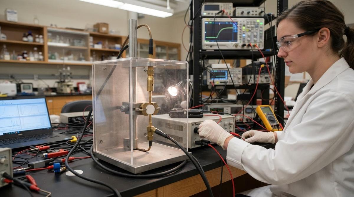
Testing follows standards such as ASTM D149 or IEC 60243-1. A voltage ramp is applied across a specimen of known thickness until current surges through it — that is the breakdown event. The breakdown voltage divided by the specimen thickness gives the dielectric strength value. Results depend on specimen thickness, temperature, electrode geometry, and ramp rate, so datasheet values should always be compared under like conditions.
Because the dielectric strength definition refers to a per-unit-thickness value, two substrates of different thickness can yield different kV/mm numbers from the same ceramic grade. Always check that comparison values were measured at the same thickness and ramp rate.
Typical Dielectric Strength Values for Ceramic Substrates
| Material | Dielectric Strength (kV/mm) | Condition | Source |
|---|---|---|---|
| Al₂O₃ 96% | 10–15 | 25 °C, 1 mm thick, per ASTM D149 | CoorsTek datasheet |
| Al₂O₃ 99.6% | 12–17 | 25 °C, 1 mm thick, per ASTM D149 | Kyocera datasheet |
| AlN | 15–17 | 25 °C, 0.635 mm thick | Maruwa datasheet |
| Si₃N₄ | 12–18 | 25 °C, 0.32 mm thick | Kyocera datasheet |
| FR-4 (for comparison) | 20–30 | 25 °C, per IPC-4101 | IPC-4101E |
Typical values for commercially available material, for comparison only. Confirm against the datasheet for your specific grade.
FR-4 has a higher dielectric strength per millimetre than most ceramics. Ceramics earn their place through superior thermal conductivity and stability at elevated temperatures — the dielectric strength of organic laminates degrades sharply above 130 °C, while alumina remains stable beyond 500 °C.
Factors That Change the Dielectric Strength Number
- Thickness. Thinner specimens report higher kV/mm values because breakdown is not purely linear with thickness. Always compare values at the same thickness.
- Temperature. Dielectric strength drops as temperature rises. A 96% alumina substrate rated at 15 kV/mm at 25 °C may fall to 8–10 kV/mm at 300 °C.
- Porosity and sintering quality. Voids inside the ceramic act as weak points where partial discharge initiates. Higher-purity, denser ceramics perform better.
- Metallization edges. Sharp conductor edges concentrate the electric field locally, reducing effective breakdown voltage of the assembly even if the bulk ceramic is adequate.
Enter your substrate material, thickness, and target working voltage below to see how temperature derating affects your available safety margin.
Why Dielectric Strength Definition Matters in PCB Design
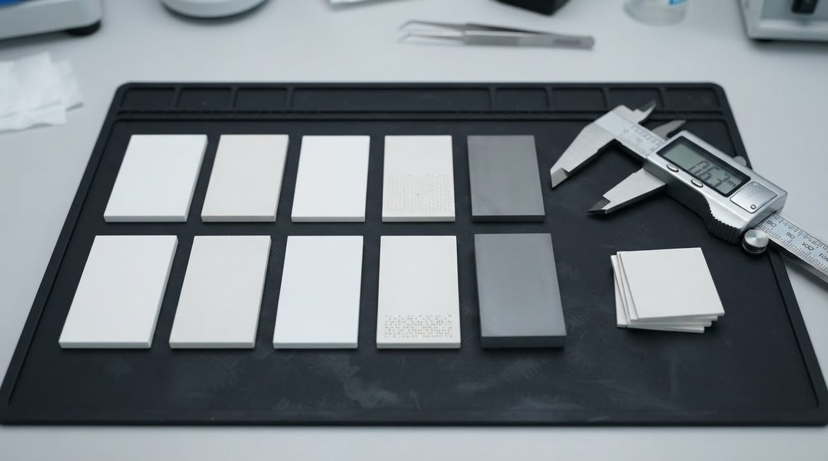
High-voltage power modules, IGBT drivers, and RF amplifiers often require creepage and clearance distances set by IEC 60664-1. Knowing the substrate’s dielectric strength lets you calculate the minimum ceramic thickness needed for a target working voltage, including safety margin. A common rule of thumb is to design for no more than 50% of the rated dielectric strength to account for ageing, temperature rise, and manufacturing variation.
For example, if your working voltage is 5 kV and you select 96% alumina with a rated dielectric strength of 12 kV/mm, the minimum theoretical thickness is 5 / 12 = 0.42 mm. Applying the 50% derating factor doubles that to 0.84 mm. A standard 1.0 mm substrate gives comfortable margin.
Related Terms
Breakdown voltage is the absolute voltage (in kV) at which failure occurs for a specific part geometry — it equals dielectric strength multiplied by thickness. Dielectric constant (εr) describes how much the material stores electric energy and affects impedance, not breakdown. The two properties are independent; a high εr does not imply high dielectric strength.
Frequently Asked Questions
Is dielectric strength the same as breakdown voltage?
No. Dielectric strength is a material property expressed per unit thickness (kV/mm), while breakdown voltage is the absolute voltage (kV) at which a specific specimen fails. Breakdown voltage equals dielectric strength multiplied by the specimen’s thickness. You need both numbers: dielectric strength to compare materials, breakdown voltage to verify a specific part geometry.
Does dielectric strength change with temperature?
Yes. Dielectric strength decreases as temperature rises. A 96% alumina substrate rated at 15 kV/mm at 25 °C may drop to 8–10 kV/mm at 300 °C. Ceramics retain useful insulation performance far longer than organic laminates like FR-4, which degrade rapidly above 130 °C, but you must still derate for your actual operating temperature.
Why does FR-4 have higher dielectric strength than alumina?
FR-4 typically rates 20–30 kV/mm versus 10–17 kV/mm for alumina grades. The organic resin matrix is inherently a strong insulator at room temperature. Ceramics compensate with thermal stability, far higher thermal conductivity (24–170 W/mK versus 0.3 W/mK for FR-4), and the ability to operate reliably above 300 °C where FR-4 cannot function at all.
How much safety margin should I apply to the dielectric strength rating?
A widely used guideline is to design for no more than 50% of the datasheet dielectric strength value. This accounts for manufacturing variation, ageing, partial discharge at metallization edges, and temperature rise during operation. For safety-critical applications governed by IEC 60664-1, consult the standard’s specific test and margin requirements for your insulation class.