Introduction to the DS1307 Real-Time Clock IC
The DS1307 is an 8-pin RTC IC manufactured by Maxim Integrated (formerly Dallas Semiconductor). It is designed to keep track of time and date information, even when the main power supply is interrupted, thanks to its built-in backup battery.
Key Features of the DS1307
- Accurate timekeeping with seconds, minutes, hours, day, date, month, and year
- 56-byte non-volatile RAM for data storage
- I2C interface for easy communication with microcontrollers
- Low power consumption
- Automatic leap year compensation
- Operating voltage range: 4.5V to 5.5V
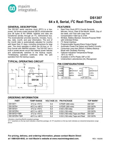
DS1307 Pinout and Pin Description
The DS1307 comes in an 8-pin DIP (Dual Inline Package) or SOIC (Small Outline Integrated Circuit) package. The following table and diagram illustrate the DS1307 pinout:
| Pin Number | Pin Name | Description |
|---|---|---|
| 1 | X1 | 32.768 kHz crystal connection |
| 2 | X2 | 32.768 kHz crystal connection |
| 3 | VBAT | Backup battery input (+3V) |
| 4 | GND | Ground |
| 5 | SDA | Serial Data (I2C data line) |
| 6 | SCL | Serial Clock (I2C clock line) |
| 7 | SQW/OUT | Square Wave/Output Driver |
| 8 | VCC | Positive supply voltage (4.5V to 5.5V) |
X1 and X2 (Pins 1 and 2)
The X1 and X2 pins are used to connect a 32.768 kHz crystal, which provides the reference clock for the DS1307. The crystal should be a low-cost, surface-mount type with a typical load capacitance of 12.5 pF.
VBAT (Pin 3)
The VBAT pin is used to connect a backup battery to the DS1307. This battery maintains the timekeeping functionality when the main power supply is disconnected. A 3V lithium coin cell battery, such as the CR2032, is commonly used for this purpose.
GND (Pin 4)
The GND pin is the ground reference for the DS1307 and should be connected to the common ground of the system.
SDA and SCL (Pins 5 and 6)
The SDA (Serial Data) and SCL (Serial Clock) pins are used for I2C communication between the DS1307 and a microcontroller. The SDA pin is bidirectional and is used for data transfer, while the SCL pin is used for clock synchronization.
SQW/OUT (Pin 7)
The SQW/OUT pin can be configured to output a square wave signal with a frequency of 1 Hz, 4 kHz, 8 kHz, or 32 kHz. This feature can be used for various purposes, such as generating a reference clock for other devices or triggering interrupts.
VCC (Pin 8)
The VCC pin is the main power supply input for the DS1307. It should be connected to a stable power source within the range of 4.5V to 5.5V, such as a regulated 5V supply.

Interfacing the DS1307 with a Microcontroller
To integrate the DS1307 into your project, you’ll need to connect it to a microcontroller using the I2C protocol. Most modern microcontrollers, such as Arduino boards or Raspberry Pi, have built-in I2C peripherals that can communicate with the DS1307.
Hardware Connections
- Connect the VCC pin of the DS1307 to the 5V power supply of your microcontroller.
- Connect the GND pin of the DS1307 to the ground of your microcontroller.
- Connect the SDA pin of the DS1307 to the SDA pin of your microcontroller.
- Connect the SCL pin of the DS1307 to the SCL pin of your microcontroller.
- Connect a 32.768 kHz crystal between the X1 and X2 pins of the DS1307.
- Optionally, connect a 3V battery to the VBAT pin for backup power.
Software Configuration
To communicate with the DS1307 using a microcontroller, you’ll need to use the appropriate libraries and functions for I2C communication. Most programming platforms, such as Arduino IDE or Raspberry Pi’s Python, have pre-existing libraries that simplify the process of interfacing with the DS1307.
Here’s an example of how to set the time on the DS1307 using Arduino IDE:
#include <Wire.h>
#include "RTClib.h"

RTC_DS1307 rtc;

void setup() {
  Serial.begin(9600);
  Wire.begin();
  rtc.begin();

  // Set the time (replace with your desired time)
  rtc.adjust(DateTime(2023, 4, 21, 12, 0, 0));
}

void loop() {
  DateTime now = rtc.now();
  Serial.print(now.year(), DEC);
  Serial.print('/');
  Serial.print(now.month(), DEC);
  Serial.print('/');
  Serial.print(now.day(), DEC);
  Serial.print(' ');
  Serial.print(now.hour(), DEC);
  Serial.print(':');
  Serial.print(now.minute(), DEC);
  Serial.print(':');
  Serial.print(now.second(), DEC);
  Serial.println();
  delay(1000);
}
In this example, the RTClib.h library is used to interface with the DS1307. The rtc.adjust() function is called in the setup() function to set the initial time, and the rtc.now() function is used in the loop() function to retrieve the current time and print it to the serial monitor.

DS1307 Registers and Data Format
The DS1307 has several internal registers that store time, date, and control information. These registers can be accessed and modified through the I2C interface.
Time and Date Registers
The DS1307 uses binary-coded decimal (BCD) format to store time and date information in its registers. The following table shows the register map for time and date:
| Register Address | Bit 7 | Bit 6 | Bit 5 | Bit 4 | Bit 3 | Bit 2 | Bit 1 | Bit 0 |
|---|---|---|---|---|---|---|---|---|
| 0x00 | CH | 10 Seconds | Seconds | |||||
| 0x01 | 0 | 10 Minutes | Minutes | |||||
| 0x02 | 12/24 | AM/PM | 10 Hours | Hours | ||||
| 0x03 | 0 | 0 | 0 | 0 | 0 | DAY | ||
| 0x04 | 0 | 0 | 10 Date | Date | ||||
| 0x05 | 0 | 0 | 0 | 10 Month | Month | |||
| 0x06 | 10 Year | Year |
The CH bit in the seconds register is the clock halt bit. When set to 1, the oscillator is disabled, and the DS1307 is in a low-power state. When set to 0, the oscillator is enabled, and the DS1307 is keeping time.
Control Register
The control register (address 0x07) is used to configure various settings of the DS1307, such as the square wave output and the rate select bits.
| Bit 7 | Bit 6 | Bit 5 | Bit 4 | Bit 3 | Bit 2 | Bit 1 | Bit 0 |
|---|---|---|---|---|---|---|---|
| OUT | 0 | 0 | SQWE | 0 | 0 | RS1 | RS0 |
- OUT: Output control bit. When set to 1, the SQW/OUT pin is driven by the INT/SQW signal. When set to 0, the SQW/OUT pin is driven by the square wave generator.
- SQWE: Square Wave Enable bit. When set to 1, the square wave generator is enabled. When set to 0, the square wave generator is disabled.
- RS1 and RS0: Rate Select bits. These bits control the frequency of the square wave output, as shown in the table below:
| RS1 | RS0 | SQW/OUT Frequency |
|---|---|---|
| 0 | 0 | 1 Hz |
| 0 | 1 | 4.096 kHz |
| 1 | 0 | 8.192 kHz |
| 1 | 1 | 32.768 kHz |
RAM Registers
The DS1307 has 56 bytes of non-volatile RAM (addresses 0x08 to 0x3F) that can be used for storing user data. This data remains intact even when the main power supply is removed, as long as the backup battery is installed.

Troubleshooting Common Issues
Incorrect Time and Date
If the DS1307 is displaying the wrong time or date, verify the following:
- Ensure that the crystal is connected correctly between the X1 and X2 pins and that it is a 32.768 kHz crystal.
- Check that the backup battery is installed and has sufficient charge.
- Verify that the time and date registers are set correctly in your code.
I2C Communication Errors
If you’re experiencing issues with I2C communication between the microcontroller and the DS1307, consider the following:
- Check the wiring connections between the microcontroller and the DS1307. Ensure that the SDA and SCL pins are connected correctly.
- Verify that the I2C address used in your code matches the DS1307’s address (0x68).
- Make sure that the I2C bus is properly initialized in your code and that the necessary libraries are included.
Square Wave Output Not Working
If the square wave output is not functioning as expected, check the following:
- Ensure that the SQW/OUT pin is connected to the appropriate pin on your microcontroller or external circuit.
- Verify that the control register is configured correctly, with the SQWE bit set to 1 and the desired frequency selected using the RS1 and RS0 bits.
- Check that the OUT bit in the control register is set to 0 to enable the square wave generator output on the SQW/OUT pin.
Conclusion
The DS1307 is a versatile and reliable RTC IC that can be easily integrated into a wide range of projects requiring accurate timekeeping. By understanding the DS1307 pinout, its registers, and how to interface it with a microcontroller, you can harness its capabilities to create time-sensitive applications, data logging systems, and more.
FAQ
-
Q: Can the DS1307 operate without a backup battery?
A: Yes, the DS1307 can operate without a backup battery, but it will not maintain time and date information when the main power supply is disconnected. -
Q: How accurate is the DS1307?
A: The accuracy of the DS1307 depends on the accuracy of the 32.768 kHz crystal used. With a typical crystal, the DS1307 has an accuracy of ±2 minutes per month. -
Q: Can I use a different crystal frequency with the DS1307?
A: No, the DS1307 is designed to work specifically with a 32.768 kHz crystal. Using a different frequency crystal will result in inaccurate timekeeping. -
Q: How long does the backup battery last?
A: The backup battery life depends on factors such as the battery type, capacity, and the DS1307’s operating conditions. A typical CR2032 lithium coin cell battery can last for several years. -
Q: Can I use the DS1307 with a 3.3V microcontroller?
A: Yes, the DS1307 is compatible with 3.3V microcontrollers, as long as the VCC pin is supplied with a voltage within the specified range (4.5V to 5.5V). You may need to use level shifters for the SDA and SCL lines if the microcontroller’s I2C pins are not 5V tolerant.


Leave a Reply