What is Circuit Trace?
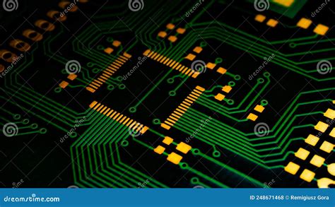
Circuit trace, also known as PCB trace or copper trace, refers to the conductive pathways that are etched or printed onto a printed circuit board (PCB) to electrically connect the various components mounted on the board. These traces are made of copper and are an essential part of any PCB design.
Circuit traces are responsible for carrying electrical signals and power between components on a PCB. They are designed to have specific widths, thicknesses, and spacing to ensure optimal signal integrity, current-carrying capacity, and to prevent signal interference.
Types of Circuit Traces
There are two main types of circuit traces:
-
Surface Traces: These traces are exposed on the outer layers of the PCB and are used for connecting components and test points.
-
Internal Traces: These traces are located within the inner layers of a multi-layer PCB and are used for interconnecting components and routing signals between layers.
Importance of Circuit Trace Design
Proper circuit trace design is crucial for the following reasons:
-
Signal Integrity: Well-designed traces ensure that signals are transmitted accurately and with minimal distortion, maintaining the integrity of the electrical signals.
-
Electromagnetic Compatibility (EMC): Proper trace design helps minimize electromagnetic interference (EMI) and ensures that the PCB complies with EMC regulations.
-
Current-Carrying Capacity: Traces must be designed with the appropriate width and thickness to handle the required amount of current without overheating or causing voltage drops.
-
Manufacturing Feasibility: Circuit traces must be designed in accordance with the capabilities of the PCB manufacturing process to ensure that the board can be produced reliably and cost-effectively.

Factors Affecting Circuit Trace Design
Several factors need to be considered when designing circuit traces:
1. Trace Width
The width of a trace determines its current-carrying capacity and its characteristic impedance. Wider traces can carry more current and have lower resistance, but they also take up more space on the PCB. The trace width is typically determined by the required current-carrying capacity and the desired characteristic impedance.
2. Trace Thickness
The thickness of a trace, also known as its height or depth, affects its current-carrying capacity and its resistance. Thicker traces can carry more current and have lower resistance, but they also increase the overall thickness of the PCB. The trace thickness is typically determined by the PCB manufacturing process and the desired current-carrying capacity.
3. Trace Spacing
The spacing between traces, also known as the trace pitch, affects the PCB’s signal integrity and its manufacturing feasibility. Traces that are too close together can cause signal crosstalk and make the PCB more difficult to manufacture. The minimum trace spacing is determined by the PCB manufacturing process and the required signal integrity.
4. Trace Routing
The routing of traces on a PCB is critical for ensuring signal integrity and minimizing signal interference. Traces should be routed as directly as possible to minimize signal reflections and should be kept away from other traces and components that could cause interference.

Circuit Trace Design Guidelines
To ensure optimal circuit trace design, follow these guidelines:
-
Use appropriate trace widths: Determine the required current-carrying capacity and characteristic impedance for each trace and select the appropriate trace width accordingly.
-
Use appropriate trace thicknesses: Select the appropriate trace thickness based on the PCB manufacturing process and the required current-carrying capacity.
-
Maintain adequate trace spacing: Ensure that traces are spaced far enough apart to minimize signal crosstalk and to facilitate manufacturing.
-
Route traces carefully: Route traces as directly as possible and keep them away from potential sources of interference.
-
Use ground planes: Use ground planes to provide a low-impedance return path for signals and to minimize signal interference.
-
Use vias appropriately: Use vias to route signals between layers and to provide thermal relief for components, but avoid using too many vias as they can affect signal integrity and increase manufacturing costs.

Common Circuit Trace Configurations
There are several common circuit trace configurations used in PCB design:
1. Microstrip
A microstrip is a trace that is routed on the outer layer of a PCB, with a ground plane on the layer below it. Microstrips are commonly used for high-speed signals and are relatively easy to manufacture.
| Parameter | Value |
|---|---|
| Trace Width | Determined by characteristic impedance and current-carrying capacity |
| Trace Thickness | Determined by PCB manufacturing process and current-carrying capacity |
| Dielectric Thickness | Determined by desired characteristic impedance |
2. Stripline
A stripline is a trace that is routed on an inner layer of a multi-layer PCB, with ground planes above and below it. Striplines provide better signal integrity than microstrips but are more difficult to manufacture.
| Parameter | Value |
|---|---|
| Trace Width | Determined by characteristic impedance and current-carrying capacity |
| Trace Thickness | Determined by PCB manufacturing process and current-carrying capacity |
| Dielectric Thickness (above and below) | Determined by desired characteristic impedance |
3. Coplanar Waveguide
A coplanar waveguide is a trace that is routed on the outer layer of a PCB, with ground traces on either side of it. Coplanar waveguides provide good signal integrity and are relatively easy to manufacture.
| Parameter | Value |
|---|---|
| Trace Width | Determined by characteristic impedance and current-carrying capacity |
| Trace Thickness | Determined by PCB manufacturing process and current-carrying capacity |
| Ground Trace Width | Determined by desired characteristic impedance |
| Gap between Trace and Ground | Determined by desired characteristic impedance |
Circuit Trace Manufacturing Processes
Circuit traces are manufactured using several different processes:
1. Etching
Etching is the most common method for manufacturing circuit traces. In this process, a layer of copper is laminated onto the PCB substrate, and then a photoresist is applied and developed to create a pattern of the desired traces. The exposed copper is then etched away using a chemical solution, leaving the desired traces behind.
2. Milling
Milling is a subtractive process in which a high-speed spinning tool is used to remove copper from the PCB substrate to create the desired traces. Milling is typically used for creating Prototype PCBs or for low-volume production.
3. Printing
Printing is an additive process in which conductive ink is printed onto the PCB substrate to create the desired traces. Printing is typically used for creating flexible PCBs or for high-volume production.
Frequently Asked Questions (FAQ)
1. What is the difference between a microstrip and a stripline?
A microstrip is a trace that is routed on the outer layer of a PCB, with a ground plane on the layer below it, while a stripline is a trace that is routed on an inner layer of a multi-layer PCB, with ground planes above and below it. Striplines provide better signal integrity than microstrips but are more difficult to manufacture.
2. What is the purpose of a ground plane in PCB design?
A ground plane is a large area of copper on a PCB layer that is connected to the ground. Ground planes provide a low-impedance return path for signals and help to minimize signal interference by providing shielding between layers.
3. What is the minimum trace width and spacing for a PCB?
The minimum trace width and spacing for a PCB depends on the PCB manufacturing process and the desired signal integrity. Typical minimum trace widths range from 0.1 mm to 0.2 mm, while typical minimum trace spacings range from 0.1 mm to 0.15 mm.
4. Can traces be routed on both sides of a PCB?
Yes, traces can be routed on both sides of a PCB. This is known as double-sided PCB design and is commonly used to increase the routing density and to provide additional flexibility in component placement.
5. What is the difference between a via and a through-hole?
A via is a small hole drilled through a PCB that is used to route signals between layers, while a through-hole is a larger hole drilled through a PCB that is used to mount through-hole components. Vias are typically filled with conductive material to provide electrical connectivity between layers, while through-holes are not filled.
Conclusion
Circuit trace design is a critical aspect of PCB design that affects signal integrity, electromagnetic compatibility, current-carrying capacity, and manufacturing feasibility. By understanding the factors that affect circuit trace design and following best practices for trace routing and configuration, designers can create PCBs that are reliable, efficient, and cost-effective to manufacture.
As PCB technology continues to evolve, designers will need to stay up-to-date with the latest techniques and tools for circuit trace design to ensure that their products meet the ever-increasing demands for performance, reliability, and functionality.


Leave a Reply