Blog
-
 Read more: Plating Simulation – our New Tool for PCB Designers
Introduction to PCB Plating Simulation Printed circuit board (PCB) design has come a long way in recent decades. With the advent of powerful computer-aided design (CAD) tools, PCB designers can now create complex, high-density boards with ease. However, one aspect of PCB design that has remained challenging is predicting and […]
-
Rayming integrates EAGLE CAD software
Posted by
–
 Read more: Rayming integrates EAGLE CAD software
Introduction to Rayming and EAGLE CAD RAYMING PCB & Assembly, a leading provider of printed circuit board (PCB) design, prototyping, and manufacturing services, has recently announced its integration of EAGLE CAD software into its design workflow. This strategic move aims to enhance Rayming’s PCB design capabilities and streamline the process […]
-
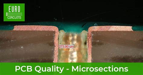 Read more: PCB Cross-Section Analysis: Technology You Want To Know
What is PCB Cross-Section Analysis? PCB cross-section analysis is a crucial technique used in the quality control and failure analysis of printed circuit boards (PCBs). It involves cutting a small section of the PCB and examining it under a microscope to assess the internal structure, layer alignment, and potential manufacturing […]
-
What is an Acid Trap in a PCB?
Posted by
–
 Read more: What is an Acid Trap in a PCB?
Introduction to Acid Traps in PCBs In the world of printed circuit board (PCB) manufacturing, acid traps are a common phenomenon that can lead to various issues during the fabrication process. An acid trap, also known as an “etch trap” or “copper trap,” is an unintended design feature that can […]
-
 Read more: FR4 Material Upgrade New Tg150 Covered ALLPCB Prototype
Introduction to FR4 and Its Significance in PCB Manufacturing FR4 (Flame Retardant 4) is a widely used material in the manufacturing of printed circuit boards (PCBs). It is a composite material composed of woven fiberglass cloth with an epoxy resin binder. FR4 has become the standard material for PCBs due […]
-
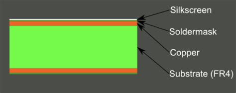 Read more: Why Silkscreen Is An Important Method Of PCB Fabrication?
What is PCB Silkscreen? PCB silkscreen, also known as legend printing or screen printing, is a method of applying text, symbols, and logos onto the surface of a printed circuit board (PCB). This process involves using a fine mesh screen to transfer ink onto the PCB, creating a durable and […]
-
What Aspects You Should Check in OQC?
Posted by
–
 Read more: What Aspects You Should Check in OQC?
Visual Inspection Visual inspection is the first and most basic aspect of OQC. It involves a thorough examination of the product’s appearance, including its color, texture, finish, and overall aesthetics. The following are some of the key points to consider during visual inspection: Surface Defects Check for any visible surface […]
-
Complete Introduction of Aluminum PCB
Posted by
–
 Read more: Complete Introduction of Aluminum PCB
What is an Aluminum PCB? An Aluminum PCB, also known as a Metal Core PCB (MCPCB), is a type of printed circuit board that uses an aluminum substrate as its base material instead of the traditional FR-4 or other non-metallic materials. The aluminum substrate provides excellent thermal conductivity, allowing for […]
-
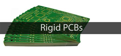 Read more: How Many Types of PCB Are in the Electronics Industry?
What is a PCB? A PCB is a flat board made of insulating material, such as fiberglass or plastic, with conductive copper traces printed on its surface. These traces connect various electronic components, such as resistors, capacitors, and integrated circuits (ICs), to form a complete electronic circuit. PCBs provide a […]
-
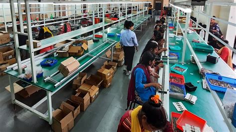 Read more: Aluminum PCB Flex and Rigid MCPCB Manufacturing At One-Stop
Introduction to MCPCB Manufacturing Metal Core Printed Circuit Boards (MCPCBs) are a specialized type of PCB that utilizes a metal substrate, typically aluminum, to enhance thermal conductivity and heat dissipation. This makes MCPCBs ideal for applications that generate significant amounts of heat, such as high-power LEDs, power electronics, and automotive […]


